
ABB IRC5 Robot Repair for Intermittent Axis Feedback
Diagnose intermittent ABB IRC5 axis feedback faults by reviewing alarm history, cables, connectors, operating conditions, and component identity.
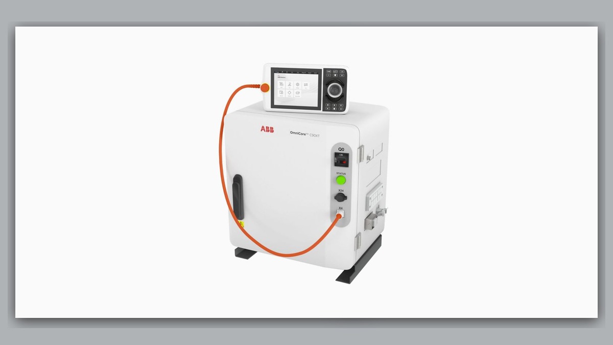
Intermittent axis feedback on an ABB IRC5 robot can involve the feedback-related component, manipulator cabling, connectors, controller interfaces, power conditions, or mechanical movement that disturbs a damaged cable. Before beginning ABB robot repair, record the complete alarm text, affected axis, robot posture, motion, load, and recurrence pattern. A feedback-related alarm or unexpected stop does not independently prove that a motor, cable, or controller board is defective. Effective diagnosis requires evidence linking the symptom to a specific operating condition and equipment configuration.
Symptoms and Scope
This diagnostic approach applies to ABB robots using an IRC5 controller when a single axis or limited group of axes develops intermittent feedback-related symptoms. Possible observations include motion interruption, an axis-specific alarm, unsuccessful motor enabling, or a fault that appears only in certain postures. The exact meaning of any displayed alarm must be checked against the documentation for the installed robot and controller software.
This article does not cover confirmed calibration loss, brake-release faults, mechanical collision damage, or a completely unpowered controller. Those conditions require different diagnostic paths. An alarm that returns after a reset is useful evidence, but resetting the controller is not a repair and should not be repeatedly used to reproduce a potentially harmful condition.
Information to Record First
Preserve the available operating evidence before disconnecting components or clearing alarm history. Maintenance personnel should record:
Complete alarm code and full text: Record every associated message in displayed order.
Date and exact time: Match the event with production and power records.
Faulted axis: Identify the axis stated by the controller.
Robot position/posture: Note the joint positions or save an approved system record.
Program step or motion: Identify the commanded operation at the stop.
Actual speed and load condition: Record the displayed or configured information without estimating it.
Reset result: State whether the alarm cleared and whether motor power could be enabled.
Time until recurrence: Record the observed interval or operating condition.
Related power, communication or feedback alarms: Preserve earlier messages that may explain the final stop.
Also identify the robot model, IRC5 controller variant, serial information, installed options, motor or feedback-related component label, cable part number, hardware revision, and connector layout. These details are necessary because similarly shaped parts are not automatically interchangeable.
Safety and Preparation
Place the robot in a safe condition according to the site risk assessment, applicable ABB operating information, and local lockout procedures. Stored energy, suspended loads, gravity-loaded axes, and nearby equipment must be controlled before inspection. Do not unplug feedback or motor connections while equipment is energized. Internal controller inspection and any observation under motion should be performed only by suitably competent personnel under controlled conditions.
Create and verify an appropriate backup before work that could affect system data. Do not change calibration values or safety parameters merely to see whether an intermittent fault disappears.
ABB Robot Repair Diagnostic Sequence
- Review the complete event sequence. Start with the earliest relevant alarm rather than the final stop message. If a power, communication, safety, or controller alarm occurred first, investigate that branch before treating the axis feedback system as the primary fault. Missing alarm history should be documented because it limits the diagnosis.
- Correlate the fault with posture and motion. Compare recorded joint positions, program steps, speed, payload condition, and recurrence timing. A fault associated with a narrow posture range may justify closer inspection of moving harness sections and connectors, but posture correlation alone does not identify the failed part. Do not cycle the robot repeatedly through a suspected damaging position solely to reproduce the alarm.
- Inspect accessible cable routes and connectors. With the equipment safely isolated, look for abrasion, crushing, sharp bending, loose retention, contamination, damaged housings, displaced seals, or signs of previous repair. Inspect both stationary and moving sections relevant to the affected axis. If no visible damage is found, the cable must not automatically be declared serviceable; internal intermittent damage may require professional testing.
- Check controller-side evidence. Confirm that connectors are correctly seated and that the installed hardware matches the documented configuration. Look for contamination, corrosion, heat discoloration, damaged contacts, or altered wiring. The inspection target should be guided by the complete alarm history and controller documentation, not by assumptions based on the affected axis alone.
- Separate electrical feedback symptoms from mechanical conditions. Abnormal noise, binding, impact history, or unexpected resistance may indicate a mechanical problem requiring a different inspection. Conversely, an intermittent feedback alarm without mechanical evidence does not confirm a gearbox or bearing fault. Stop further motion if the available evidence suggests that continued operation could increase damage.
- Evaluate suspect components off the machine when on-site evidence is insufficient. Cable assemblies, motors, feedback-related components, and controller electronics may require controlled inspection or bench testing. The exact model, part number, hardware revision, and connector layout must be verified before repair or substitution. Installing an unmatched spare can introduce configuration problems and obscure the original diagnosis.
Common Diagnostic Mistakes
Replacing the motor solely because the alarm names an axis can waste time and leave a damaged cable or controller interface unresolved. Other common mistakes include clearing logs before recording them, overlooking an earlier power or communication alarm, moving connectors without documenting their original positions, and assuming that a successful reset proves the system is healthy.
Robot maintenance records should also be reviewed for recent motor replacement, harness work, controller service, collision recovery, or manipulator disassembly. A timing relationship can guide inspection, although it does not by itself prove responsibility or component failure.
When Professional Inspection May Be Appropriate
Professional industrial robot repair may be appropriate when the fault is intermittent, internal cable damage is suspected, controller electronics require testing, or the site lacks suitable test equipment. Information about ABB controller inspection is available at https://autonews.best/products/abb-irc5-kong-zhi-gui-yu-ji-xiu. Broader ABB robot repair capabilities are described at https://autonews.best/abb-robot-repair.
ZHB is an independent industrial robot inspection, repair, and maintenance service provider that also supplies parts to overseas customers. For one repair inquiry, provide the robot model, controller model, complete alarm code and text, alarm history, component label, fault conditions, and clear photographs of the controller identification, relevant connectors, cable condition, and component labels.
Verification After Repair or Replacement
After approved work, confirm that all connectors, cable supports, covers, grounding provisions, and protective elements have been restored to the documented configuration. Verify that no tools or loose materials remain in the work area. Review the alarm log before enabling motion.
Controlled functional verification should follow the applicable operating information and site safety procedure. Competent personnel should initially use restricted conditions appropriate to the site, confirm normal axis behavior, and check whether the original alarm returns during necessary production-representative movement. Do not deliberately recreate a condition believed likely to damage the cable or robot. Calibration and positional checks are required when the completed repair or manufacturer procedure indicates that position data may have been affected.
Conclusion
Intermittent ABB IRC5 axis feedback faults require a documented, condition-based diagnosis. Alarm order, axis identity, robot posture, cable condition, connector integrity, hardware configuration, and repair history provide stronger evidence than a reset result alone. A component should be repaired or replaced only after the available observations support that decision and the replacement identity has been verified.