
FANUC Robot Repair: R-30iB Amplifier Identification
Identify a suspected FANUC R-30iB servo amplifier correctly, preserve fault evidence, and separate external causes before requesting repair.
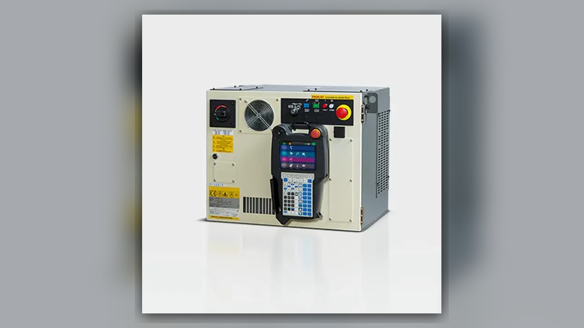
A FANUC robot repair involving a suspected R-30iB servo amplifier should begin with fault evidence and exact component identification, not immediate replacement. Servo power loss, an axis that cannot enable, or an intermittent stop may involve the amplifier, incoming power, safety chain, controller connections, motor power cable, feedback-related components, configuration, or another axis-specific condition. Before diagnosis, record the complete alarm, affected Group and Axis, operating state, and equipment labels. The symptom alone does not prove that the servo amplifier is damaged.
Symptoms and Scope
This guide applies to FANUC robot systems using an R-30iB-family controller when maintenance personnel suspect a servo amplifier and need to prepare for inspection, repair, or replacement. The precise controller variant, robot model, installed options, and amplifier identity must still be confirmed from the equipment labels and applicable documentation.
The procedure is not an alarm-specific troubleshooting sequence. If the event log contains a complete FANUC alarm code, follow the diagnostic order defined for that alarm before concluding that the amplifier is responsible. Motor noise, mechanical binding, feedback faults, safety interruptions, and damaged cables also require their own evidence-based branches. An axis that remains stationary or a controller that removes servo power cannot independently identify the failed component.
Information to Record First
Preserve the original fault evidence before clearing alarms or disconnecting hardware. Maintenance records should include:
Complete alarm code and full text:
Date and exact time:
Faulted axis:
Robot position/posture:
Program step or motion:
Actual speed and load condition:
Reset result:
Time until recurrence:
Related power, communication or feedback alarms:
Also record the robot model, controller model, amplifier part number, hardware revision, connector layout, and any recent maintenance or cable work. Photograph the component label and installed connections clearly enough to establish orientation. Do not rely on cabinet appearance alone because visually similar units may differ in rating, revision, configuration, or application.
Safety and Preparation
Place the robot in a controlled maintenance state according to the FANUC documentation for the installed system and the factoryâÂÂs lockout and energy-control procedure. Qualified personnel must address stored electrical energy, suspended loads, gravity-affected axes, tooling, and nearby machinery before cabinet inspection or component removal.
Do not open the servo amplifier, probe energized internal circuits, bypass safety devices, or change parameters merely to test a replacement theory. If observation under motion is necessary, it may be performed only by suitably competent personnel under controlled conditions and in accordance with the applicable manufacturer operating information and site safety procedure. Do not repeatedly recreate an event that could increase equipment or production risk.
FANUC Robot Repair Diagnostic Sequence
- Review the complete event history. Identify the first relevant alarm rather than concentrating only on the final servo-off message. An earlier power, safety, communication, feedback, or axis alarm may establish a different diagnostic branch. If the history is incomplete, preserve the available records and state that limitation in the repair inquiry.
- Confirm the equipment identity. Compare the controller nameplate, robot model, installed servo amplifier label, part number, hardware revision, and connector arrangement. The decision point is whether the physical component matches the documented system configuration. Any discrepancy must be resolved before ordering, exchanging, or installing a unit.
- Inspect external conditions with power safely isolated. Look for loose or incompletely seated connections, contamination, damaged cable jackets, discolored connectors, blocked cabinet cooling paths, missing fasteners, and evidence of earlier cabinet work. A visible defect may justify cable or connection inspection, but it does not automatically establish internal amplifier damage.
- Separate system-wide and axis-specific behavior. Determine whether all axes lose servo power, one axis is implicated by the event history, or the problem appears only in a particular posture or operating stage. A system-wide event can direct attention toward shared power, safety, or controller functions. A posture-dependent event can support inspection of moving cables and connectors. These observations guide the next check but remain diagnostic clues rather than final proof.
- Evaluate the suspected amplifier only after external evidence has been reviewed. Appropriate professional assessment may include controlled inspection and testing based on the exact amplifier model and manufacturer service information. If the required documentation, test equipment, or competence is unavailable on site, preserve the unitâÂÂs identification and fault records for specialist evaluation instead of attempting internal repair.
When Repair or Replacement May Be Considered
Professional amplifier repair may be considered when the documented diagnostic path continues to implicate the unit, the part can be identified precisely, and external causes have been reasonably separated. Replacement may be appropriate when a verified compatible unit is available and the factoryâÂÂs recovery procedure can be followed. Neither choice should be based solely on a servo-off symptom.
Match any spare by exact model, part number, hardware revision, and connector layout. Confirm configuration requirements through the documentation for the installed robot and controller. A repaired or replacement amplifier should not be treated as interchangeable merely because it fits mechanically or uses similar connectors.
For evaluation of an identified R-30iB component, the FANUC R-30iB servo amplifier repair service page is available at https://autonews.best/products/fanuc-r-30ib-si-fu-qi-ji-xiu. ZHB is an independent industrial robot inspection, repair, and maintenance service provider that also supplies parts to overseas customers; it does not imply manufacturer authorization.
Verification After Repair or Replacement
Before restart, verify connection security, cabinet condition, cable routing, protective covers, and completion of the siteâÂÂs safety checks. Confirm that the correct component has been installed and that no tools or disconnected conductors remain in the cabinet.
Review the alarm history after controlled power-up and confirm whether the original event returns. Functional verification should begin under the lowest-risk conditions permitted by the applicable FANUC instructions and site procedure. Qualified personnel should check servo enable, affected-axis response, programmed motion, and operation under the approved production load without deliberately reproducing a hazardous fault. Record the result and any new alarm in the maintenance history.
Information Required for a Repair Inquiry
Provide the controller model, robot model, complete alarm code, full alarm history, component label, fault conditions, and clear photographs. Include the affected Group and Axis where available, recent maintenance details, recurrence pattern, and photographs of the amplifier label and installed connectors. This information helps distinguish an amplifier inspection request from a cable, controller, safety, or axis-system problem.
Conclusion
Accurate FANUC robot repair begins by preserving alarms, identifying the exact R-30iB hardware, and separating external system causes before removing the servo amplifier. A disciplined evidence trail reduces incompatible part selection and unnecessary replacement. Repair or replacement should follow only when the applicable diagnostic information supports further amplifier evaluation.