
Industrial Robot Repair: Servo Enable Failure Diagnosis
Diagnose an industrial robot that will not enable its servos after a stop by checking safety status, interlocks, power, alarms, and drive readiness.
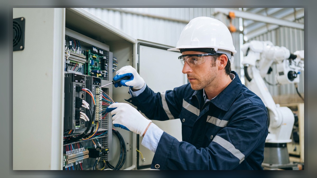
An industrial robot that will not enable its servos may have an active safety condition, an incomplete external interlock, missing drive power, a connection problem, or a controller configuration issue. Before diagnosis, record the complete alarm text, controller state, operating mode, affected axes, and events immediately preceding the stop. A servo-enable failure does not independently prove that a servo amplifier, motor, or safety component is damaged. The controller may simply be preventing motion because one required permission is absent.
Symptoms and Scope
This diagnostic process applies to general ABB, FANUC, KUKA, and YASKAWA industrial robot systems that complete at least part of their startup sequence but do not reach a servo-ready or motors-on state. Brand-specific terminology varies: a controller may refer to motor power, servo power, drive enable, motion enable, or readiness.
The process is not intended for a controller that is completely unpowered, a robot with confirmed mechanical seizure, or a system with a manufacturer-defined alarm requiring a separate procedure. Always use the maintenance documentation for the installed robot and controller generation.
A failed enable command can appear as a rejected motors-on request, immediate return to motors-off status, an active safety message, or a drive that never becomes ready. These observations identify the fault stage, but they do not identify the failed component.
Information to Record First
Preserve the evidence before resetting alarms or cycling power. Alarm history often reveals an earlier event that explains why servo power remains inhibited.
Complete alarm code and full text:
Date and exact time:
Faulted axis:
Robot position/posture:
Program step or motion:
Actual speed and load condition:
Reset result:
Time until recurrence:
Related power, communication or feedback alarms:
Also record the robot model, controller model, software version if available, operating mode, and whether the failure followed maintenance, cable work, a collision, a power interruption, or a safety-device activation. If multiple alarms are present, retain their original sequence rather than documenting only the final servo-enable message.
Safety and Preparation
Place the equipment in a safe condition according to the manufacturer’s instructions and the site lockout procedure. Do not bypass an emergency-stop channel, guard circuit, enabling device, safety PLC, or external interlock to force servo operation. Stored electrical and mechanical energy may remain after power is isolated.
Visual inspection and diagnostic-screen review should be performed only by suitably competent personnel. Cabinet access, electrical measurements, and component removal require the appropriate training, protective equipment, and equipment-specific maintenance information. Do not repeatedly request motor power when unexplained noise, overheating, smoke, damaged wiring, or unexpected movement has been observed.
Robot Maintenance Diagnostic Sequence
- Identify the first relevant alarm. Review the controller event history and external machine logs. Determine whether a safety, power, communication, feedback, or configuration alarm occurred before the servo-enable failure. When an earlier alarm exists, investigate that event first. The later enable message may only describe the controller’s protective response.
- Confirm the operating state. Check the selected mode, emergency-stop status, guard status, teach pendant enabling-device state, and any required reset sequence. For an automatic cell, verify that the robot has received the required external permissions from the cell controller or PLC. A displayed reset indication does not prove that every channel and external permission has returned to a valid state.
- Inspect external safety and control connections. Look for loose plugs, damaged cables, bent connector hardware, contamination, or recently disturbed wiring. Compare the installed connections with the electrical drawings for that exact cell. If the failure began after maintenance, identify every connector, panel, or device that was handled. Do not assume that a connector is correct merely because it can be physically inserted.
- Review controller and drive readiness. Use the controller’s supported diagnostic pages to determine whether logic power is present, the safety chain is satisfied, and the drive system reports readiness. The available indications and their meanings depend on the controller model and software. Record the displayed states before replacing hardware. If drive readiness is absent, follow the manufacturer’s sequence for that controller rather than applying another brand’s procedure.
- Check the power path without unsupported live testing. Inspect visible circuit protection, disconnect status, contactor condition indicators, and power-related alarms. Qualified personnel may perform measurements only when the applicable manual provides the method, measurement points, expected condition, and safety controls. Missing drive power can originate upstream and should not automatically be classified as amplifier failure.
- Separate system-wide and axis-specific evidence. If no axis can enable, prioritize shared safety permissions, common power, controller communication, and system configuration. If one axis is identified by an earlier alarm, investigate that axis using the relevant manufacturer procedure. Motor, feedback, brake, cable, and mechanical branches should be opened only when the alarm history or inspection evidence supports them.
- Review recent changes. Confirm whether software, parameters, options, safety configuration, external I/O logic, or hardware was changed. Restore data only from a verified backup that matches the installed system. Do not alter safety or drive parameters as an exploratory test.
How to Distinguish Similar Causes
A safety-chain problem is more likely when the controller explicitly reports an open safety condition or when a required safety status remains invalid. An external-interlock problem is more likely when the robot itself is ready but the cell controller withholds a motion permission. A common power problem may affect all drives and appear with power-related events. An axis-specific cable, feedback-related component, motor, or mechanical problem normally requires supporting axis-specific alarms or physical evidence.
Intermittent operation after a reset is not proof of repair. It may indicate a loose connection, temperature-sensitive component, unstable external signal, or another condition that has temporarily cleared. Preserve the event log and operating conditions instead of repeatedly resetting the system.
When Repair or Replacement May Be Considered
Professional component inspection may be appropriate when the diagnostic sequence isolates a suspect controller board, safety unit, power supply, servo amplifier, pendant, or cable assembly. Before sourcing a spare, match the exact model, part number, hardware revision, software requirements, and connector layout. Similar-looking components are not necessarily interchangeable.
ZHB is an independent industrial robot inspection, repair, and maintenance service provider that also supplies parts to overseas customers. General service information is available at https://autonews.best/services. An inquiry should include the robot model, controller model, complete alarm code, alarm history, component label, fault conditions, and clear photographs of the controller, connectors, and suspected component.
Verification After Repair or Replacement
After corrective work, confirm that guards, emergency stops, enabling devices, interlocks, cabinet covers, and protective connections have been restored. Check that the controller starts without unexplained alarms and that the expected safety and drive-ready states are present.
Any motion verification must be performed by competent personnel under controlled conditions and in accordance with the manufacturer’s operating information and the site safety procedure. Begin with the approved low-risk commissioning process. Verify relevant mastering, calibration, payload, tooling, and program conditions if the repair could have affected them. Do not reproduce a hazardous event merely to test whether it returns.
Conclusion
Effective industrial robot repair starts by identifying which permission is missing from the servo-enable sequence. Alarm chronology, safety status, external interlocks, power availability, drive readiness, and recent changes provide stronger evidence than replacing the first suspected component. A disciplined robot maintenance record also helps distinguish a recoverable operating condition from a repeatable hardware or connection fault.