
KUKA Robot Maintenance: Controller Repair Readiness
Use a structured KUKA robot maintenance routine to identify controller risks, preserve fault evidence, and decide when professional repair is justified.
In this article
KUKA robot maintenance should identify controller risks before they become production faults. A preventive review can involve the controller cabinet, teach pendant, cables, cooling path, power connections, software records, and alarm history. Before inspection, record the robot model, controller model, cabinet identification, operating conditions, and any active or historical messages. Visible dust, heat marks, loose connections, or a failed restart can indicate a maintenance issue, but none of these observations alone proves that a specific controller board, power supply, drive, or cable is damaged.
Symptoms and Scope
This guide covers preventive maintenance and repair-readiness checks for general KUKA industrial robot systems, including installations using KUKA controllers such as KR C4 where applicable. Exact inspection points depend on the installed controller, robot, software version, electrical options, external axes, safety equipment, and site design. It does not replace the applicable KUKA documentation or authorize live electrical work.
The objective is to detect evidence that supports a controller repair decision. It is not a procedure for changing safety parameters, bypassing protective circuits, or replacing a part based only on a single alarm or visual symptom.
Information to Record First
Create a compact maintenance record before clearing messages or changing connections.
Complete alarm code and full text: Record the exact displayed wording and any associated diagnostic information.
Date and exact time: Note when the symptom was observed and when it began.
Faulted axis: Identify the axis or external axis if the controller identifies one.
Robot position/posture: Record the position only when it can be obtained safely and accurately.
Program step or motion: Note the active operation, tool, workpiece, and sequence stage.
Actual speed and load condition: Record the operating condition shown by the controller or production system.
Reset result: State whether a reset changed the symptom, without treating reset success as a repair.
Time until recurrence: Record recurrence timing if the issue returns during normal authorized operation.
Related power, communication or feedback alarms: Include messages that appeared before or with the primary symptom.
KUKA Robot Maintenance Before Controller Repair
Begin with identification. Confirm the robot model, controller model, cabinet label, teach pendant identification, and any connected external axes or peripheral controllers. This information determines which service documentation, circuit layout, spare parts, and diagnostic methods apply. If the equipment identity is incomplete, stop the repair decision and obtain clear identification photographs or records.
Next, review the alarm history and operating conditions. Compare the current message with earlier events, recent cabinet work, software changes, power interruptions, environmental exposure, and changes to connected equipment. A controller startup problem following service may involve a connection or configuration issue, while a recurring fault under a specific motion may require a broader review. These are diagnostic possibilities, not confirmed causes.
Inspect the cabinet externally and internally only under the site isolation procedure and by personnel qualified for the work. Look for restricted cooling airflow, contamination, moisture evidence, unusual odor, discoloration, damaged cable entries, loose mounting, and visible connector or harness damage. Do not touch energized assemblies or perform measurements unless the applicable KUKA documentation, equipment design, and site electrical controls support that work.
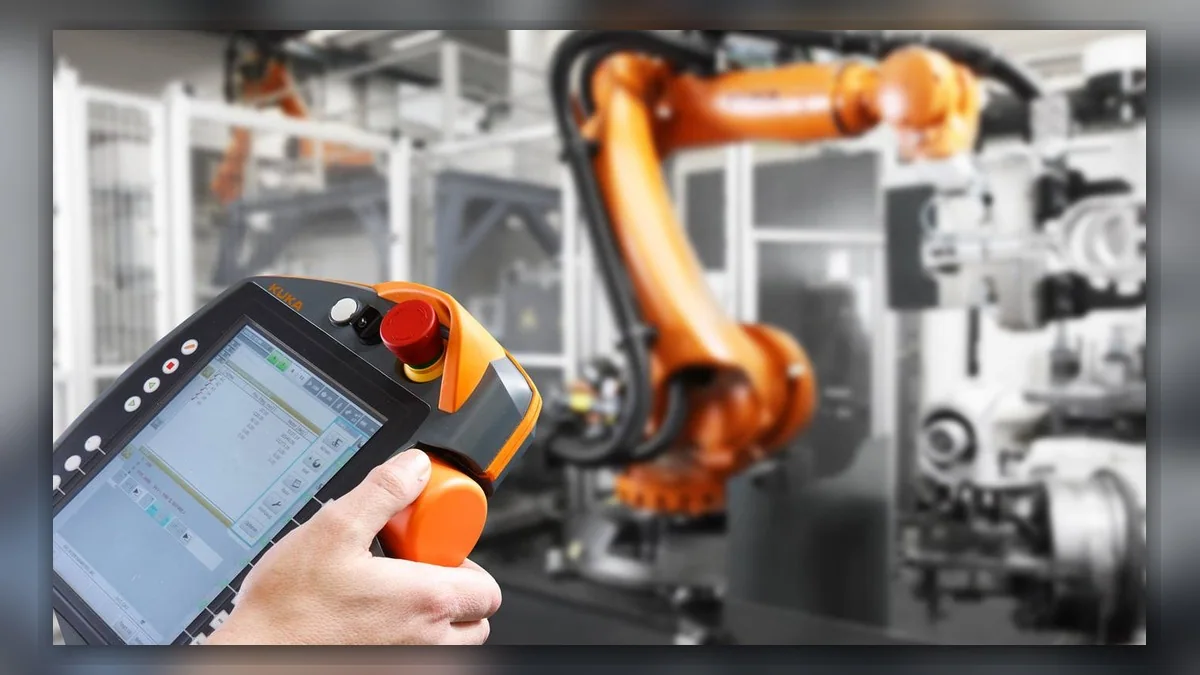
Check the teach pendant and controller interface for physical damage, intermittent input, display problems, or communication symptoms. Compare the observed behavior with alarm history and with the condition of connected devices. A working display does not prove that the controller power, drive, safety, or communication circuits are healthy. Similarly, a blank display does not independently identify a failed display, power supply, or controller board.
Controller Repair Decision Points
Professional evaluation should be considered when the same controller symptom returns after documented external checks, when the cabinet shows contamination or thermal damage, when diagnostic evidence points to an internal assembly, or when the required test cannot be completed safely on site. Before ordering a spare, match the exact controller model, assembly or part number, hardware revision, software requirements, and connector layout. Confirm that the proposed component belongs to the installed configuration. A replacement part should not be selected merely because it has a similar appearance or a compatible-sounding description.
When inspection requires energized testing, board-level diagnosis, controlled restart, or work inside the cabinet, use suitably competent personnel under the manufacturer information and site safety procedure. Motion observation may be performed only under controlled conditions, with guarding, authorization, and risk controls in place. Do not repeatedly restart or reproduce a fault when doing so could increase equipment risk.
Information Required for a Repair Inquiry
Provide the robot model, controller model, complete alarm code and text, alarm history, component label, fault conditions, and clear photographs of the cabinet, identification plates, connectors, and affected area. Also provide the Group and Axis where shown, the alarm time, recent service history, and any relevant power or communication event. ZHB provides independent industrial robot inspection, repair, and maintenance services and supplies parts to overseas customers; repair suitability is determined from the installed equipment and available evidence.
Verification After Repair or Replacement
After repair or replacement, verify that the installed component matches the approved model, part number, hardware revision, and connector layout. Check that covers, cooling paths, cable routing, grounding, protective devices, and external connections have been restored according to the applicable documentation. Clear and document the previous fault only after the repair record is complete. Perform a controlled restart and confirm controller status, safety status, communication, axis readiness, and program behavior within the permitted test conditions. Record any remaining message rather than assuming that the absence of an immediate alarm proves long-term reliability.
Conclusion
Effective KUKA robot maintenance connects preventive inspection with disciplined controller evidence. Accurate equipment identification, complete alarm records, controlled cabinet inspection, and configuration-matched parts reduce the risk of replacing the wrong assembly. When internal testing or restart verification exceeds site capability, a qualified repair assessment is the appropriate next step.
Need a part or repair assessment?
Share the robot model, part number, fault details and destination country with our team.
Contact our team ↗