
Yaskawa Robot Repair After Controller Contamination
Learn how to document, inspect, and troubleshoot contamination inside a Yaskawa robot controller without assuming that a drive or board has failed.
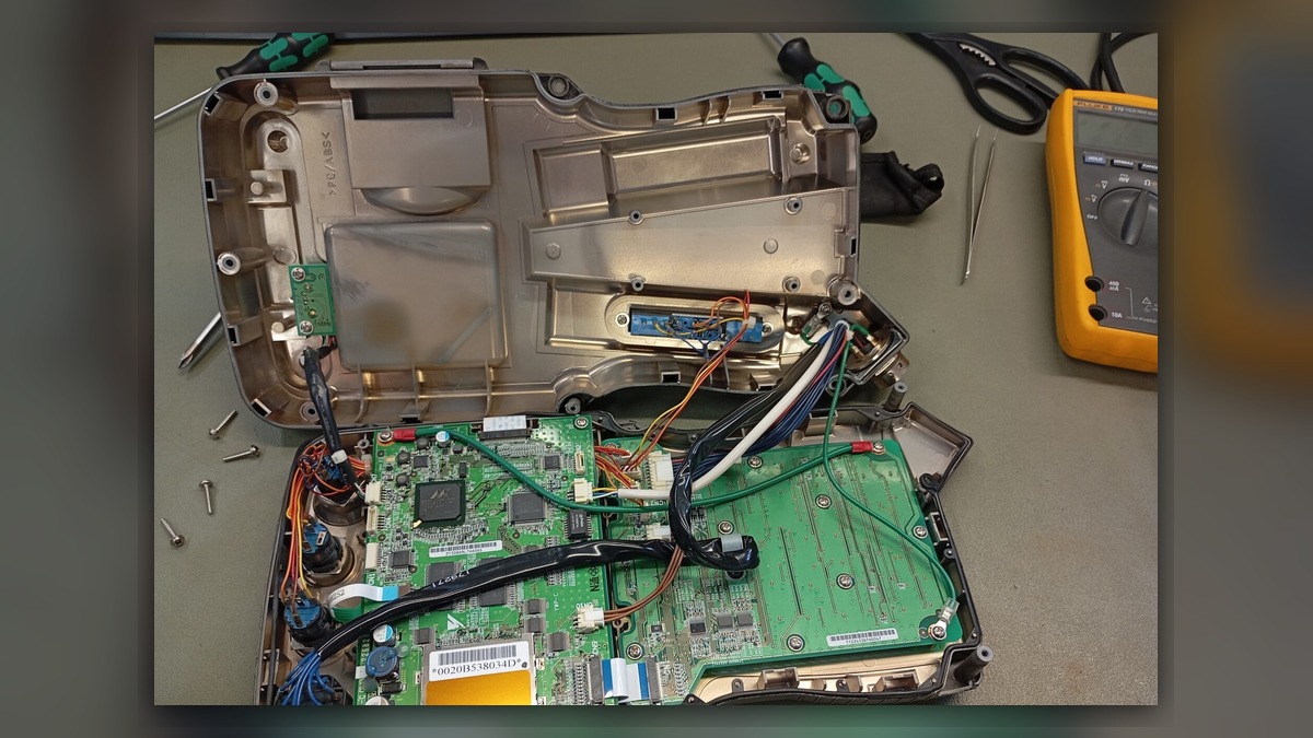
Yaskawa robot repair after controller contamination should begin with safe isolation, fault documentation, and identification of the material that entered the cabinet. Dust, oil mist, coolant, conductive debris, and condensation can affect power distribution, cooling, connectors, circuit boards, and drive components. Record the complete alarm history, controller model, robot model, and operating conditions before cleaning or resetting anything. A shutdown, servo fault, or communication alarm following contamination does not independently prove that a circuit board, power supply, or servo drive is damaged.
Symptoms and Scope
This diagnostic approach applies to clearly identified Yaskawa industrial robot systems where contamination is visible inside the controller or where exposure is strongly supported by site evidence. Relevant observations may include wet residue, accumulated conductive dust, oil film, corrosion, blocked ventilation paths, discolored connectors, unusual odor, or recurring faults after a spill or high-humidity event.
The process does not establish a universal repair procedure for every Yaskawa controller generation. Cabinet construction, board arrangement, connector locations, cooling systems, and approved service procedures vary by controller model and configuration. It also does not cover contamination limited to the manipulator, teach pendant, external positioner, welding equipment, or field wiring unless evidence connects those systems to the controller fault.
Information to Record First
Preserve the original evidence before cleaning, disconnecting cables, or repeatedly attempting a restart. Photographs should show the complete cabinet, the contamination path, affected components, connector positions, cable labels, and component identification plates.
Complete alarm code and full text: Record every displayed message without abbreviation.
Date and exact time: Use the controller record or plant event log when available.
Faulted axis: Record the group and axis if the event identifies one.
Robot position/posture: Note the stopped position without moving the robot solely to reproduce the fault.
Program step or motion: Identify the command active before the event.
Actual speed and load condition: Record available production information without estimating missing values.
Reset result: State whether the alarm cleared, remained active, or returned.
Time until recurrence: Record the observed interval if the machine was safely restarted.
Related power, communication or feedback alarms: Preserve earlier alarms as well as the final stopping alarm.
Safety and Preparation
Follow the applicable Yaskawa operating and maintenance information, site lockout procedure, and electrical safety requirements. Qualified personnel should isolate all relevant energy sources and account for stored electrical energy before opening or inspecting the controller. Do not energize equipment that remains wet, contains loose conductive debris, or shows evidence of burned insulation or damaged protective devices.
Do not use compressed air indiscriminately. It can push contamination beneath components, into connectors, or across energized clearances. Do not apply general-purpose cleaners to boards, labels, seals, plastics, or coated assemblies unless material compatibility and the approved cleaning method have been confirmed. Evidence preservation should come before cleaning because residue patterns may help identify the entry path and affected zone.
Yaskawa Robot Repair Diagnostic Sequence
- Confirm the exposure. Identify whether the material is water, coolant, oil, dust, metal particles, smoke residue, or an unknown substance. Determine where it entered and whether the source is still active. If the material cannot be identified, treat compatibility and conductivity as unknown and obtain specialist guidance before cleaning.
- Define the affected boundary. Inspect ventilation openings, filters, fans, cable entries, door seals, upper cabinet surfaces, and nearby plant equipment. Determine whether contamination is localized or distributed by airflow. A dirty filter alone does not prove that internal electronics are damaged, while a clean exterior does not exclude entry through a cable gland or open cabinet door.
- Review alarms chronologically. Compare the first recorded alarm with later servo, communication, safety, or power alarms. The earliest event may identify the affected system more accurately than the final shutdown message. Record missing log information rather than reconstructing an unsupported sequence.
- Perform a controlled visual inspection. Look for residue beneath connectors, corrosion, tracking marks, damaged conformal coating, blocked heat sinks, contaminated fan blades, loose debris, and changed connector color. Do not disconnect multiple plugs without labeling and photographing their original positions. Connector appearance alone cannot confirm an internal electrical failure.
- Separate contamination from unrelated causes. Verify external power condition, grounding, cabinet environment, cable security, cooling condition, and recent maintenance history. A fault occurring after contamination may still originate from a loose connection, failed fan, damaged external cable, configuration issue, or separate machine event.
- Decide the service level. Surface contamination that has not entered assemblies may require a different response from liquid beneath components, corrosion inside connectors, or conductive debris around power electronics. Suspect assemblies may need professional cleaning, controlled drying, inspection, and bench testing. Replacement should be considered only when damage, failed testing, unavailable repair support, or repair economics justify it.
Component Identification and Repair Decisions
Before sending a board, power supply, drive, or controller assembly for service, record its exact model, part number, hardware revision, and connector layout. Similar-looking assemblies are not automatically interchangeable. Software compatibility, option configuration, safety functions, and controller generation must also be verified through applicable technical information.
ZHB is an independent industrial robot inspection, repair, and maintenance service provider that also supplies parts to overseas customers. General service information is available at https://autonews.best/services. A repair inquiry should include the Yaskawa robot model, controller model, complete alarm code, alarm history, component label, fault conditions, contamination type, and clear photographs of the cabinet, affected area, connectors, and identification plates.
Verification After Repair or Cleaning
Before restart, confirm that the contamination source has been corrected, all inspected connectors are restored to their documented positions, protective covers are installed, cooling paths are clear, and no tools or loose material remain inside the cabinet. Verify backups and configuration records according to the applicable controller procedure before replacing or exchanging configured assemblies.
Initial energization and motion checks should be performed only by suitably competent personnel under controlled conditions, following manufacturer information and the site safety procedure. Review the alarm history, controller status, cooling operation, safety functions, communication, and axis enable condition before production motion. Where permitted, use a controlled low-risk test program and monitor for recurrence without deliberately recreating a spill, short circuit, overload, or unsafe operating condition.
Common Diagnostic Mistakes
Common errors include resetting alarms before saving the event log, cleaning away evidence before identifying the entry path, replacing the last component named by an alarm, and assuming that visible residue proves internal failure. Other mistakes include installing a visually similar spare without checking its full identification, reconnecting unlabeled plugs incorrectly, and returning the robot to production without correcting damaged seals, ventilation problems, leaking process equipment, or environmental exposure.
Conclusion
A reliable contamination repair begins with evidence, not parts replacement. Identify the substance and entry path, preserve alarms and photographs, define the affected area, inspect without spreading the material, and distinguish contamination-related damage from power, cable, cooling, communication, configuration, and mechanical causes. Professional testing may be appropriate when residue has entered connectors or electronic assemblies. Final verification should confirm both safe robot operation and elimination of the environmental condition that caused the exposure.