
Yaskawa Robot Repair for Intermittent Servo-Off Events
Diagnose intermittent Yaskawa robot servo-off events by reviewing alarms, safety inputs, power conditions, connections, and axis-specific evidence.
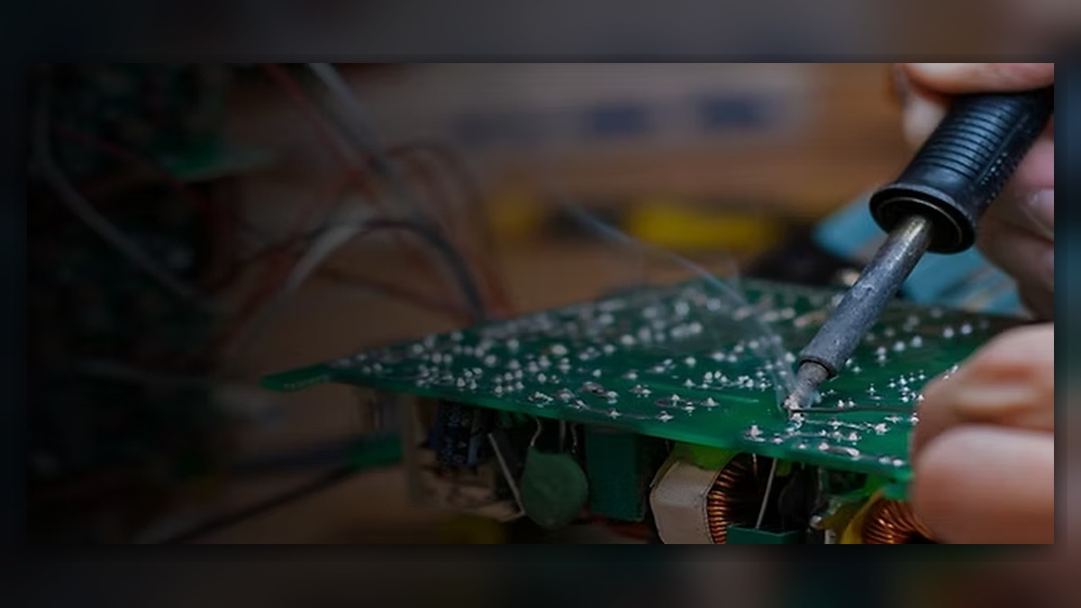
An intermittent servo-off event requires Yaskawa robot repair when motor power drops unexpectedly or cannot remain enabled. Potentially involved systems include the external power supply, controller power section, safety circuit, servo system, cables, and connected peripherals. Before diagnosis, record the complete alarm text, time, operating mode, robot posture, program position, and affected axis. A servo-off symptom alone does not prove that a servo amplifier, motor, or controller board is damaged; the controller may be responding correctly to an external safety or power condition.
Symptoms and Equipment Scope
This diagnostic approach applies to Yaskawa industrial robot systems that intermittently lose servo power during production, teaching, or an enable command. The exact controller model, robot model, software configuration, and installed safety options must be identified before controller-specific procedures are selected.
Typical observations may include an unexpected stop during motion, failure to retain servo power after reset, or successful restarting followed by recurrence. Determine whether all axes lose servo power together or whether the event is associated with one axis, posture, tool operation, or program step. A system-wide event may direct attention toward power, safety, or controller-level conditions. Axis-specific evidence may justify closer inspection of the relevant motor, drive channel, feedback-related component, and cable path.
This article does not establish the meaning of any particular alarm code. Always use the maintenance information applicable to the installed Yaskawa controller and robot combination.
Information to Record First
Preserve the evidence before clearing alarms or cycling power. Alarm history often provides more useful direction than the final visible message because an earlier event may have initiated the servo-off state.
Complete alarm code and full text:
Date and exact time:
Faulted axis:
Robot position/posture:
Program step or motion:
Actual speed and load condition:
Reset result:
Time until recurrence:
Related power, communication or feedback alarms:
Also record the robot model, controller model, serial identifiers, software information where available, end-of-arm tooling, recent maintenance, and any changes to external equipment. Note whether the event began after cable work, fixture changes, a collision, cabinet service, or production-line modifications. These facts are diagnostic inputs, not proof of causation.
Safety and Preparation
Stop automatic production and secure the work area according to the site lockout, energy-control, and robot safety procedures. Stored electrical and mechanical energy may remain after the main supply is isolated. Cabinet access, electrical measurements, brake release, and internal component inspection must be performed only by suitably qualified personnel using the applicable Yaskawa documentation.
Do not repeatedly run the robot merely to reproduce an intermittent stop. If observation under motion is necessary, suitably competent personnel should conduct it under controlled conditions and in accordance with the manufacturerâÂÂs operating information and the site safety procedure.
Yaskawa Robot Repair Diagnostic Sequence
- Review the complete alarm sequence. Use the event time and alarm history to identify the first relevant message, not only the alarm remaining after the stop. If a power, safety, communication, or feedback alarm appears first, follow that diagnostic branch. If history is incomplete, preserve controller records before further resets.
- Establish the event scope. Determine whether servo power drops on every axis, one control group, or one axis. Compare the event with operating mode, robot posture, program step, tool command, and external machine state. If the event consistently follows an external interlock transition, investigate that interface before removing servo hardware.
- Inspect external power and visible condition. With the equipment safely isolated, check the facility supply connection, disconnects, protective devices, grounding arrangements, and accessible cabinet connections for looseness, contamination, discoloration, or physical damage. Confirm whether other equipment recorded a power interruption at the same time. Do not infer acceptable power quality solely because the controller can restart.
- Evaluate the safety chain. Review emergency-stop devices, gate circuits, enabling devices, external safety equipment, and controller safety status using configuration-specific information. Determine whether the controller removed servo power because a safety input changed state. A resettable safety event does not by itself prove a defective safety board; field wiring, contacts, connectors, and external devices may also require inspection.
- Examine cables and connectors. After safe isolation, inspect accessible controller, base, dress-pack, motor, and feedback connections relevant to the recorded scope. Look for strain, crushed sections, contamination, poor retention, bent hardware, or heat damage. A posture-dependent event can support a cable investigation, but posture alone cannot identify the failed conductor or component.
- Separate controller-wide and axis-specific evidence. If all axes are affected without an initiating external event, qualified technicians may need to evaluate controller power and servo-enable functions using the correct maintenance manual. If evidence remains limited to one axis, compare that axis with its drive channel, motor connections, cable path, load condition, and associated alarms. Mechanical binding should be considered only when motion behavior, load evidence, or relevant alarms support that branch.
When Repair or Replacement May Be Considered
Professional component testing may be appropriate when alarm history and inspection consistently identify a controller module, servo drive, motor, cable assembly, teach pendant, or safety-related unit. Repair or replacement should not be selected solely because servo power disappeared. Intermittent faults are especially vulnerable to unnecessary parts replacement when external inputs and connectors have not been excluded.
Before sourcing a spare, match the exact component model, part number, hardware revision, connector layout, and controller compatibility. Preserve software, parameter, calibration, and backup information according to the applicable procedure before changing controller hardware. ZHB is an independent industrial robot inspection, repair, and maintenance service provider that also supplies parts to overseas customers; relevant service information is available at https://autonews.best/services.
Verification After Repair or Maintenance
After corrective work, confirm that guards, connectors, grounding provisions, covers, and safety devices have been restored. Review the alarm history, verify that the intended configuration and backups remain valid, and test safety functions under the approved site procedure. Begin with controlled checks before returning to automatic production.
Where motion verification is required, use a cleared work area, an appropriate operating mode, and a suitably competent operator. Confirm servo enabling, low-risk commanded motion, axis behavior, tooling interaction, and the original operating condition without deliberately creating a hazardous event. Record the repair action and verification result so recurrence can be compared with the original evidence.
Common Diagnostic Mistakes
Common mistakes include replacing a servo amplifier from the final symptom alone, clearing the alarm history before recording it, overlooking an earlier safety or power event, and assuming a successful reset proves the fault is resolved. Other errors include moving connectors without labeling them, installing a visually similar spare without checking revision details, and changing parameters to suppress a symptom without establishing the cause.
Information Required for a Repair Inquiry
For a focused repair inquiry, provide the Yaskawa robot model, controller model, complete alarm code and text, full alarm history, component label, fault conditions, and clear photographs of the cabinet and relevant component labels. Include the event time, affected axis, robot posture, program stage, reset behavior, recurrence interval, recent maintenance, and whether the event affects one axis or the complete robot. This information helps determine whether on-site diagnosis, component testing, repair, or replacement evaluation is the appropriate next step.
Conclusion
Intermittent servo-off events require evidence-based diagnosis across power, safety, connection, controller, drive, and axis-specific systems. Recording the first alarm and operating condition is more reliable than replacing the component most closely associated with the final symptom. A controlled Yaskawa robot maintenance process should preserve evidence, use configuration-specific documentation, verify part identity, and define safe restart checks before production resumes.