
ABB Servo Motor Repair for Connector Heat Damage
Learn how to assess heat-damaged ABB servo motor connectors, separate cable faults from motor damage, and prepare evidence for professional repair.
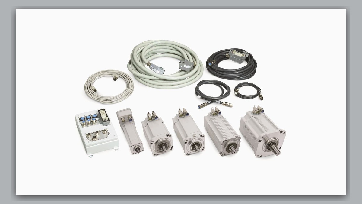
ABB servo motor repair may be required when a motor connector shows discoloration, deformation, damaged contacts, or signs of localized overheating. Potentially involved areas include the motor receptacle, mating cable connector, contact termination, cable strain relief, and adjacent insulation. Before diagnosis, record the complete alarm, affected axis, robot position, operating condition, and motor identification. Visible heat damage does not independently prove that the motor windings, brake, or feedback-related component have failed; the initiating problem may be on either side of the connection.
Symptoms and Equipment Scope
This diagnostic approach applies to ABB robot axis motors where visible connector damage, an intermittent axis fault, or a loss of motor operation directs attention to the motor-to-cable interface. The exact connector arrangement depends on the robot model, motor assembly, controller generation, axis, and installed cable configuration.
Relevant observations may include connector discoloration, softened or distorted housing material, damaged seals, recessed contacts, looseness at the mating interface, or contamination around the connector. An odor or visible mark can identify an area requiring inspection, but it cannot establish the internal condition of the motor.
This article does not cover a connector that is visibly intact with no evidence linking the fault to the motor interface. It also does not assume that an axis alarm is a motor fault. Controller drive electronics, robot cabling, configuration, mechanical loading, and other connections may produce similar symptoms.
Information to Record First
Preserve the alarm history before clearing faults or disconnecting equipment. Maintenance personnel should record:
Complete alarm code and full text:
Date and exact time:
Faulted axis:
Robot position/posture:
Program step or motion:
Actual speed and load condition:
Reset result:
Time until recurrence:
Related power, communication or feedback alarms:
Also record the ABB robot model, controller model, motor part number, motor serial information when available, cable identification, and whether either connector had recently been disturbed. Clear photographs should show the complete motor label, connector layout, mating cable plug, contact area, and surrounding cable condition.
Safety and Preparation
Stop the robot according to the applicable ABB operating information and the facility lockout procedure. Stored energy, suspended axes, gravity-loaded mechanisms, and automatic restart hazards must be controlled before a connector is handled. Do not disconnect or reconnect motor cables while the system is energized.
Do not repeatedly reset or run an axis merely to reproduce a connector heating event. Continued operation could increase damage to contacts, insulation, or nearby components. Electrical and insulation testing should be performed only by competent personnel using procedures appropriate to the exact motor and controller configuration.
ABB Servo Motor Repair Diagnostic Sequence
First, review the complete event history. Determine whether the connector finding followed a motor power, drive, feedback, communication, or temperature-related alarm. The earlier alarm may define the correct diagnostic branch more accurately than the final stop message. If no relevant alarm was retained, the missing history should be noted rather than replaced with an assumed cause.
Second, inspect both halves of the disconnected interface. Compare the motor receptacle with the cable plug for uneven discoloration, damaged locking features, contamination, displaced contacts, or evidence that the connector was not fully seated. Damage concentrated on the cable side supports inspection of the cable assembly and termination. Damage extending into the motor receptacle may require motor assessment, but it still does not confirm internal winding or feedback damage.
Third, inspect the accessible cable route for crushing, excessive tension, loss of strain relief, abrasion, or movement near the connector. Record whether the alarm occurs only in a particular robot posture. A posture-dependent symptom can support investigation of the moving cable system, although controlled observation under motion may be performed only by suitably competent personnel following site safety procedures and the applicable manufacturer information.
Fourth, verify component identity before separating parts for service. The motor model, ABB part number, hardware revision, connector orientation, connector layout, brake arrangement, and feedback interface must match the installed application. Similar-looking motors or connectors should not be treated as interchangeable without confirmed compatibility.
How to Distinguish Cable and Motor-Side Damage
A damaged cable plug, loose cable termination, or compromised strain relief may indicate that the cable assembly requires repair or replacement. A damaged motor receptacle may justify professional motor inspection to determine whether a connector-level repair is technically appropriate.
Associated feedback alarms may require examination of the feedback circuit and its connections. They do not, by themselves, prove failure of a feedback-related component inside the motor. Likewise, a drive alarm does not prove that the servo amplifier is defective. The alarm sequence, visual evidence, cable condition, and component test results must be considered together.
Mechanical resistance at the robot joint can also increase motor demand, but connector appearance alone cannot identify a brake, bearing, reducer, or joint problem. If abnormal resistance, noise, or axis movement is reported, the mechanical system should be assessed separately before a motor-only repair decision is made.
When Repair or Replacement May Be Considered
Professional ABB servo motor repair may be considered when damage reaches the motor receptacle, internal leads, insulation, brake circuit, or feedback interface, or when suitable testing cannot be completed safely on site. The repair scope should be based on inspection and test findings rather than the external appearance alone.
Replacement may be appropriate when damage is not repairable to an acceptable standard or when the correct replacement is operationally preferable. Any spare must be matched by exact model, part number, hardware revision, shaft and mounting arrangement, brake configuration, feedback interface, and connector layout. Calibration or axis data requirements must be confirmed for the installed robot before return to production.
For broader controller, robot, and axis inspection needs, the ABB robot repair service overview is available at https://autonews.best/abb-robot-repair. ZHB is an independent industrial robot inspection, repair, and maintenance service provider that also supplies parts to overseas customers; it does not imply manufacturer authorization.
Verification After Repair or Replacement
Before energizing the robot, verify connector engagement, locking, cable support, protective covers, and routing. Confirm that tools and temporary test equipment have been removed and that all safety controls are restored through the facility’s approved process.
Review the alarm display at startup and confirm that no new motor power, brake, communication, or feedback alarm is present. Any controlled movement should begin under restricted conditions and be performed only by competent personnel. Check the affected axis through an approved functional test without deliberately recreating the damaging condition. Final acceptance should include alarm-history review and confirmation that robot calibration, positioning, and safety functions meet the site’s requirements.
Information Required for a Repair Inquiry
A useful repair inquiry should include the robot model, controller model, complete alarm code and text, alarm history, motor label, fault conditions, and clear photographs of both connector halves. Include the affected axis, robot posture, program stage, recurrence pattern, cable identification, and any observed contamination or mechanical damage. This evidence helps an industrial robot repair service distinguish a cable problem, connector repair, motor inspection, or wider ABB robot repair requirement without assuming that the motor is defective.
Conclusion
Connector heat damage requires the complete motor and cable interface to be evaluated. Record the alarm sequence, isolate the equipment safely, inspect both connector halves, and verify the exact component identity. A damaged connector can justify professional ABB servo motor repair, but it does not independently confirm failure of the motor windings, brake, feedback-related component, or servo drive.