
FANUC Robot Repair: SRVO-021 HRDY and SRDY Triage
Learn how to troubleshoot FANUC SRVO-021 SRDY OFF by recording alarm data, checking HRDY and SRDY status, and separating power, wiring, and drive causes.
In this article
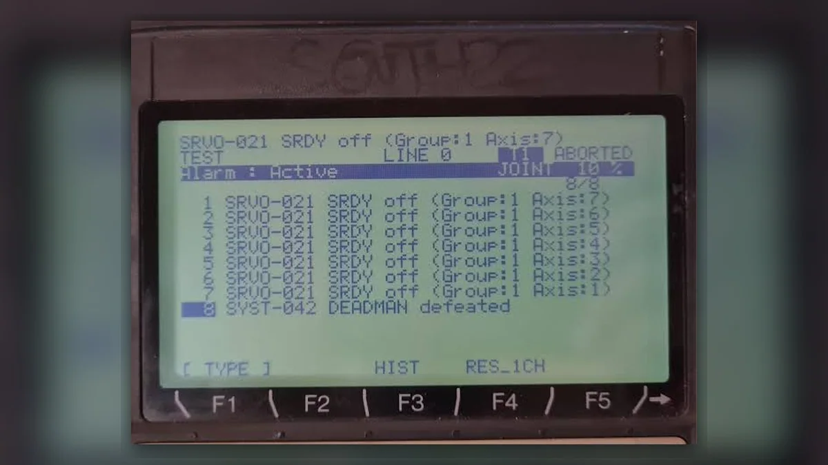
FANUC robot repair for SRVO-021 SRDY OFF should begin with evidence, not immediate amplifier replacement. On the FANUC R-30iB Mate and R-30iB Mate Plus controller scope covered by maintenance manual B-83525EN/07, the defined condition is that HRDY is ON while SRDY remains OFF, no other alarm explains the state, and the servo amplifier magnetic contactor did not turn on as commanded. Record the complete alarm, Group, Axis, event time, and operating conditions first. This symptom does not independently prove that the servo amplifier is damaged because the diagnostic path also includes earlier alarms, configuration-specific connections, emergency-stop equipment, and a possible instantaneous power interruption.
Symptoms and Scope
This guide addresses SRVO-021 SRDY OFF on FANUC R-30iB Mate and R-30iB Mate Plus controllers. Connector locations, signal paths, and inspection procedures depend on the installed controller configuration and the exact manual revision. The alarm definition and sequence should not automatically be applied to other FANUC controller families, other alarm codes, or another robot brand. A robot that will not servo on may have a related earlier alarm that must be resolved before SRVO-021 can be interpreted correctly.
Information to Record First
Complete alarm code and full text: Include SRVO-021 SRDY OFF and the displayed Group and Axis information.
Date and exact time: Record when the alarm occurred and whether it followed startup, reset, program selection, or another event.
Faulted axis: Record the Group and Axis shown by the controller.
Robot position/posture: Record the stationary position or posture when available.
Program step or motion: Record the program step, motion, or operating mode associated with the event.
Actual speed and load condition: Record the operating state and load condition without estimating missing values.
Reset result: State whether reset cleared the alarm temporarily, failed immediately, or produced another alarm.
Time until recurrence: Record the elapsed time before recurrence when this information is available.
Related power, communication or feedback alarms: Include the full alarm history before and after SRVO-021.
Safety and Preparation
Follow the site lockout, isolation, and electrical safety procedure before inspecting cabinet wiring or power equipment. Do not remove covers, probe live circuits, reset safety devices, or operate the robot under motion unless the work is permitted by the applicable manufacturer information and performed by suitably competent personnel. Keep the controller model, robot model, software or maintenance manual revision, cabinet configuration, and component labels available before comparing connections. Do not repeatedly reset the controller merely to reproduce the fault if doing so could increase equipment risk.
Diagnostic Sequence for FANUC Robot Repair
First, confirm the complete SRVO-021 text, Group, Axis, alarm time, and alarm history. The input is the controller record; the target is the sequence and any earlier alarm. If another alarm appears earlier or explains the servo-off state, treat SRVO-021 as a consequence until the earlier condition is evaluated. If no earlier alarm explains the state, continue with the HRDY and SRDY condition documented for the applicable controller.
Next, confirm the controller and robot identifiers and inspect the external condition without disturbing wiring. Look for visible connector damage, loose hardware, contamination, heat damage, or signs of cabinet service. The decision point is whether the observed condition matches the installed configuration. If the configuration cannot be identified, stop before applying connector-specific instructions and obtain the missing cabinet documentation or clear photographs.
Then confirm HRDY and SRDY status from the diagnostic screen or maintenance records when those signals are available. The relevant condition is HRDY ON with SRDY OFF. This confirms the defined SRVO-021 state, but it does not identify the failed component. If the status does not match, record the actual display and review the alarm interpretation for the installed controller and manual revision.
After that, check the configuration-specific connections and the possibility that an instantaneous power interruption occurred. The input should include the event log, site power event information, and cabinet configuration. The decision condition is whether a documented interruption coincided with the alarm or whether a connection concern is visible. If either condition is supported, correct the verified site or connection issue according to the applicable procedure and reassess the alarm history. Do not expand this step into an unsupported conclusion about voltage fluctuation or abnormal contactor behavior.
If the earlier checks do not explain the condition, evaluate the emergency-stop unit and servo amplifier in the priority order defined by the applicable maintenance manual. The target is the command and response path associated with the magnetic contactor, not simply the amplifier label. A result that identifies a damaged connection, emergency-stop unit issue, or amplifier-side fault should be documented before repair consideration. If the evidence remains incomplete, professional diagnostic testing is more appropriate than forced part replacement.
How to Distinguish Similar Causes
SRVO-021 is not a standalone proof of amplifier failure. An earlier alarm, an emergency-stop circuit condition, a configuration-specific connection issue, or an instantaneous power interruption may produce the same practical symptom of servo enable being unavailable. Motor, feedback-related, or mechanical investigation should be expanded only when another earlier or associated alarm supports that branch. A single reset that temporarily clears the display is not proof that the underlying cause has been removed.
When Repair or Replacement May Be Considered
Repair or replacement may be considered after the complete alarm history, HRDY/SRDY evidence, configuration details, and relevant inspection results have been reviewed. Match any proposed spare by exact model, part number, hardware revision, and connector layout. Do not substitute a visually similar amplifier or connector assembly without confirming compatibility from the applicable documentation. For component-level evaluation of an R-30iB servo amplifier, the relevant ZHB service reference is https://autonews.best/products/fanuc-r-30ib-si-fu-qi-ji-xiu. The page should support identification and inquiry, not replace controller-specific diagnosis.
Verification After Repair or Replacement
Before returning the robot to production, verify that the repair or replacement matches the documented controller configuration and that all covers, connectors, guards, and safety functions are restored according to site procedure. Review the alarm history, confirm that the previous cause has been addressed, and perform controlled servo-enable and motion checks only by suitably competent personnel under the manufacturer operating information and site safety procedure. Confirm that no new alarm appears and that the robot remains stable through the intended operating sequence. Do not repeat a risky motion solely to reproduce SRVO-021.
Information Required for a Repair Inquiry
ZHB is an independent industrial robot inspection, repair, and maintenance service provider that also supplies parts to overseas customers. For an inquiry, provide the controller model, robot model, complete SRVO-021 alarm code and text, Group and Axis, full event log, alarm time, connector photographs, and servo-amplifier label. Add HRDY/SRDY information only when it can be obtained safely from the diagnostic screen or maintenance records. Clear photographs of the cabinet identification plate, relevant connectors, and visible damage can help determine what information is still missing.
Sources and Update Information
The alarm definition and diagnostic priority in this article are based on FANUC America Corporation, FANUC Robot series R-30iB Mate/R-30iB Mate Plus Controller Maintenance Manual, B-83525EN/07, SRVO-021 SRDY off, page 73. An accessible copy is hosted by Haas Automation at https://www.haascnc.com/content/dam/haascnc/en/service/reference/fanuc-manuals/Fanuc%20Robot%20Series%20R-30iB%20Mate%20%2B%20Mate%20Plus%20Maintenance%20Manual.pdf. Connector names and locations should be used only after the exact controller configuration and matching manual version have been confirmed.
Conclusion
A disciplined FANUC robot repair assessment for SRVO-021 separates the defined HRDY/SRDY condition from the cause of that condition. Record the alarm and axis data, identify any earlier alarm, verify the applicable configuration, investigate possible instantaneous power interruption, and then evaluate the emergency-stop unit and servo amplifier in the documented order. This evidence-based sequence reduces the risk of replacing an amplifier before the actual fault path is established.
Need a part or repair assessment?
Share the robot model, part number, fault details and destination country with our team.
Contact our team ↗