
Industrial Robot Repair for a Single Axis That Will Not Move
Diagnose a single robot axis that will not move by separating safety, drive, cable, feedback, brake, motor, and mechanical causes before replacing parts.
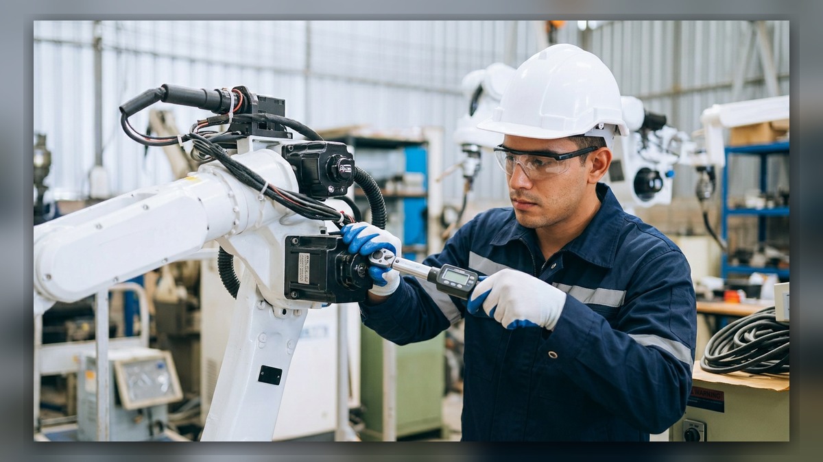
When one industrial robot axis will not move, the fault may involve motion permission, a servo drive channel, motor power, feedback wiring, a holding brake, or the mechanical transmission. Before diagnosis, record the complete alarm, controller and robot models, affected axis, posture, load, and operating mode. A stationary axis does not independently prove that the motor, drive, brake, or reducer has failed. Industrial robot repair should begin by identifying where the motion command stops, without repeatedly attempting movement or replacing components without supporting evidence.
Symptoms and Scope
This diagnostic approach applies when one axis of a general ABB, FANUC, KUKA, or YASKAWA industrial robot remains stationary while the controller is operating. The axis may fail during controlled jogging or during an automatic cycle. The method also applies when the controller accepts a motion request but the affected joint does not respond normally.
It does not replace brand-specific alarm procedures, brake-release instructions, mastering procedures, or electrical measurements. If several axes cannot move, the investigation should first consider system-level conditions such as safety status, servo enable, operating mode, and shared drive power rather than treating the event as an isolated axis failure.
Information to Record First
Preserve the original evidence before clearing alarms, cycling power, or disconnecting components. Alarm history may show whether a feedback, drive, communication, power, or safety event occurred before the axis stopped.
Complete alarm code and full text:
Date and exact time:
Faulted axis:
Robot position/posture:
Program step or motion:
Actual speed and load condition:
Reset result:
Time until recurrence:
Related power, communication or feedback alarms:
Also record the robot model, controller model, serial number, installed external axes, and any recent maintenance. Note whether the symptom began after a collision, cable replacement, motor work, controller repair, tooling change, relocation, or extended shutdown. These details determine which diagnostic branch is relevant.
Safety and Preparation
Stop automatic production and secure the work area under the site lockout and energy-control procedure. Consider the effects of gravity and stored mechanical energy. A vertical or heavily loaded axis may move unexpectedly if its brake, motor, or transmission is disturbed.
Do not unplug motor, brake, or feedback connectors while equipment is energized. Covers, connectors, and modules should be accessed only by suitably competent personnel following the applicable manufacturer documentation. Do not release a brake merely to determine whether an axis can move unless the robot and load are properly supported and the approved procedure specifically requires that test.
Industrial Robot Repair Diagnostic Sequence
1. Confirm the controller state. Record whether servo power can be enabled and whether other robot axes respond normally. If no axis moves, investigate shared safety, controller, drive-power, and external-interlock conditions first. If only one axis is affected, continue with the axis-specific evidence.
- Review the complete alarm sequence. Identify the earliest relevant event rather than relying only on the final alarm displayed. A preceding feedback, communication, power, or safety alarm may explain why motion was inhibited. If the history is incomplete, preserve the available logs and obtain the correct controller maintenance documentation before proceeding.
- Verify command conditions. Confirm that the requested motion is permitted in the selected operating mode and that the programmed direction is not blocked by a configured limit or active interlock. Check whether the fault appears in manual operation, automatic operation, or both. Do not change safety limits or motion parameters as a troubleshooting shortcut.
- Inspect accessible connections. With power isolated according to the approved procedure, examine the affected axis cable path, cabinet connections, motor-side connectors, and any intermediate junctions that are part of the installed configuration. Look for loose locking mechanisms, damaged housings, contamination, corrosion, pin displacement, crushed cable sections, or evidence of excessive flexing. Connector names and locations vary by robot and controller model.
- Consider posture and cable movement. If the axis fails only in a particular robot posture, document that posture without repeatedly moving into a potentially damaging condition. Position-dependent behavior can support investigation of a moving cable or connector, but it does not by itself identify the exact conductor or prove that the motor is defective.
- Separate brake and mechanical resistance from electrical inhibition. Relevant observations include whether the axis remains locked, produces abnormal sound, or stops at a repeatable position. These observations must be interpreted with the alarm history and manufacturer procedure. A locked axis can result from a brake that has not been released, absent brake control, mechanical obstruction, or internal transmission damage. It is not sufficient evidence to order a brake or reducer.
- Evaluate the drive, motor, and feedback branch only when the evidence supports it. A drive-related alarm may originate from the drive channel, motor circuit, feedback-related component, cabling, connection, or mechanical load. Component testing should use the correct documentation and suitable test equipment. Unsupported live probing and improvised cable bypasses can damage equipment or defeat protective functions.
When Repair or Replacement May Be Considered
Professional testing may be appropriate when inspection finds connector damage, suspected cable discontinuity, a drive channel that cannot operate correctly, brake-related evidence, motor abnormalities, or mechanical resistance. Before selecting a spare, match the exact model, part number, hardware revision, electrical rating, and connector layout. Similar-looking motors, amplifiers, and cables are not necessarily interchangeable.
Replacement should follow diagnosis rather than substitute for it. If a removed drive, motor, or cable is sent for industrial robot repair, provide the associated alarms and operating conditions so the workshop can select meaningful inspection targets.
Verification After Repair or Maintenance
After approved work is completed, restore all guards and connections and confirm that no tools or temporary restraints remain. Verify controller startup, safety status, alarm history, brake operation, and axis response using the manufacturer procedure. Any controlled motion observation should be performed only by competent personnel at an appropriate speed and with the work area protected.
Check the affected axis through an approved limited motion range before returning to production. Confirm that no related alarm returns and that cables do not pull, twist, or contact surrounding equipment. If a motor, feedback-related component, reducer, or axis cable was changed, determine whether mastering, calibration, or accuracy verification is required for that specific robot.
Information Required for a Repair Inquiry
ZHB is an independent industrial robot inspection, repair, and maintenance service provider that also supplies parts to overseas customers. For an inquiry, provide the robot model, controller model, complete alarm code, alarm history, component label, fault conditions, and clear photographs of the robot, connectors, and relevant part labels. Industrial robot repair service information is available at https://autonews.best/services.
Conclusion
A single stationary robot axis is a symptom, not a component diagnosis. Effective robot maintenance preserves the alarm sequence, confirms whether the problem is system-wide or axis-specific, inspects configuration-specific connections, and separates command inhibition from brake, drive, motor, feedback, cable, and mechanical possibilities. Repair or replacement should be based on documented evidence, followed by controlled safety and motion verification.