
KUKA Robot Repair for a Single Axis Overheating
Diagnose a hot KUKA robot axis by separating load, brake, cable, motor, drive, and mechanical causes before selecting parts for repair.
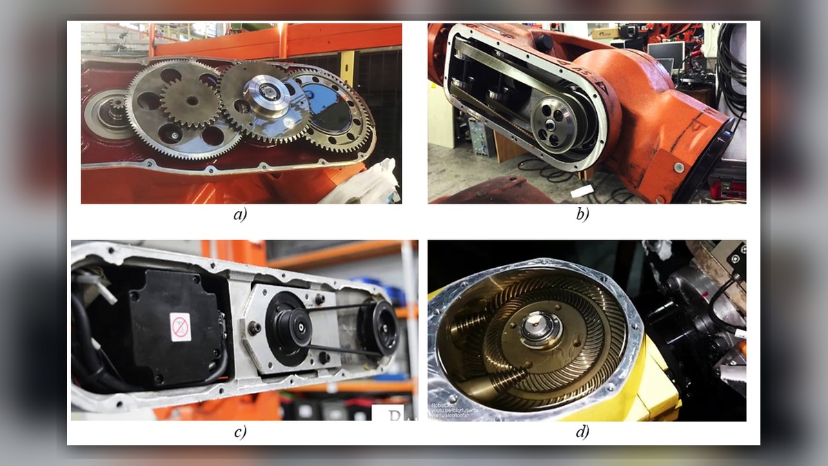
A KUKA robot axis that becomes unusually hot may involve excessive mechanical load, a brake that is not fully releasing, damaged motor or feedback wiring, a motor defect, a drive problem, or deteriorating joint mechanics. Before beginning KUKA robot repair, record the complete message history, affected axis, robot posture, motion, speed, payload, and time until the symptom appears. Temperature alone does not prove that the servo motor is damaged because operating duty, ambient conditions, cabinet cooling, and mechanical resistance can produce similar symptoms.
Symptoms and Scope
This diagnostic approach applies to a clearly identified KUKA robot with one axis showing abnormal heat, recurring temperature-related messages, reduced motion performance, or behavior that changes as the machine warms. The controller generation, robot model, motor identification, and installed options must be confirmed before consulting model-specific service information.
The procedure is not intended to establish a universal acceptable temperature. A meaningful limit requires the applicable KUKA documentation, the identified component, and a defined measurement point and operating condition. A surface reading taken after an unknown duty cycle cannot independently confirm an internal motor fault.
Information to Record First
Preserve evidence before resetting messages or changing production conditions. Useful records include:
Complete alarm code and full text:
Date and exact time:
Faulted axis:
Robot position/posture:
Program step or motion:
Actual speed and load condition:
Reset result:
Time until recurrence:
Related power, communication or feedback alarms:
Also record the robot serial information, controller model, motor label, payload and tooling condition, recent maintenance, collision history, and ambient conditions. Note whether the heat appears during continuous motion, holding, braking, or shortly after motor power is enabled. These distinctions help determine which inspection branch is appropriate.
Safety and Preparation
Stop production under the siteâÂÂs approved isolation and lockout procedure. Allow components to cool before inspection, and account for stored energy, suspended tooling, gravity-loaded axes, and hot surfaces. Do not disconnect motor, brake, feedback, or drive connections while energized. Internal controller inspection and any observation under motion must be performed only by suitably competent personnel under controlled conditions, following the applicable KUKA operating information and site safety procedure.
KUKA Robot Repair Diagnostic Sequence
Begin by reviewing the alarm history rather than treating the latest message as the root cause. An earlier brake, feedback, drive, communication, or power message may provide a more useful diagnostic direction. Save the complete sequence and timestamps before clearing the log.
Confirm the operating conditions next. Compare the programmed motion, payload definition, installed tool, process forces, and production cycle with the approved application data. If the symptom began after a tool change, collision, program revision, cable replacement, or maintenance activity, document that change. Do not alter payload or servo-related settings merely to suppress the symptom.
With power safely isolated, inspect the affected axis and its accessible cable route. Look for crushed cable sections, abrasion, contamination, loose connector housings, displaced seals, corrosion, or evidence of overheating. Compare relevant accessible connections with an unaffected area only when the controller and robot design make that comparison valid. Connector locations and inspection procedures depend on the installed KUKA configuration.
Inspect the controller cooling path and visible drive area for blocked filters, failed ventilation, contamination, or heat discoloration. A hot cabinet environment can affect drive operation, but visible heat near a drive does not prove that the drive caused the axis symptom. Record the cabinet condition and related messages before deciding whether electrical bench testing is required.
Evaluate the mechanical side without forcing the robot through unapproved movements. Check for collision evidence, damaged dress cables, tool interference, external process loads, joint leakage, or unusual resistance reported during authorized maintenance checks. A brake that does not fully release can increase motor load, while bearing or reducer deterioration may also create heat. Neither possibility should be declared from temperature alone.
How to Distinguish Similar Causes
A symptom linked to a particular posture may direct attention toward moving cables, external interference, gravity loading, or joint mechanics. A symptom that follows a recent tooling or payload change requires verification of the application data and physical load. Related feedback messages support investigation of the feedback circuit, connections, and feedback-related components. Brake messages or restricted release behavior support a brake-system branch.
If the axis heats while holding position, technicians should review the posture, external force, brake behavior, motor current evidence available through approved diagnostics, and mechanical loading. If it heats mainly during repeated acceleration, review the duty cycle and load before condemning the motor. These patterns narrow the investigation but are not component-level proof.
When KUKA Servo Motor Repair May Be Considered
Professional motor inspection may be appropriate when verified evidence remains after external loading, cooling, accessible connections, configuration, drive, and mechanical causes have been evaluated. The removed motor should be identified by its exact part number, model, hardware revision, connector layout, and brake or feedback configuration. Electrical, brake, feedback, bearing, and contamination findings should be assessed using appropriate controlled test equipment and the applicable specifications.
Replacement should not be selected solely because the housing feels hot. If a spare is considered, verify compatibility against the complete component label and robot configuration. Similar appearance is not sufficient evidence of interchangeability.
Verification After Repair or Replacement
After authorized work, confirm that protective covers, grounding provisions, connectors, cable restraints, and cooling components have been restored correctly. Review the controller log during a controlled restart. Verify mastering or calibration status only through the applicable KUKA procedure when the completed work could affect it.
Qualified personnel may then perform limited functional checks under controlled conditions, beginning conservatively and following the siteâÂÂs restart plan. Confirm axis motion, brake behavior, feedback stability, payload configuration, and absence of recurring messages before returning to production. Do not repeatedly run a potentially damaging cycle simply to reproduce overheating.
Information Required for a Repair Inquiry
ZHB is an independent industrial robot inspection, repair, and maintenance service provider that also supplies parts to overseas customers. For an inquiry through https://autonews.best/services, provide the KUKA robot model, controller model, complete alarm code, alarm history, component label, fault conditions, and clear photographs. Include the affected axis, operating posture, payload, recent service history, time until recurrence, and photographs of relevant connectors or visible damage when they can be obtained safely.
Conclusion
Effective KUKA robot repair for a hot single axis depends on separating application load, brake, cable, cooling, drive, motor, and mechanical causes. Preserve the alarm sequence and operating conditions first, then use configuration-specific information to narrow the fault. Component repair or replacement should follow evidence and exact identification, not temperature or an isolated message alone.