
KUKA Robot Repair After a Collision or Tool Impact
A structured KUKA robot repair process for checking position, tooling, cables, joints, motors, and motion after a collision or tool impact.
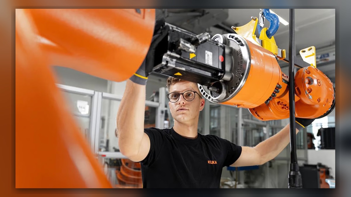
A KUKA robot that has experienced a collision or tool impact should be inspected before normal production resumes. Potentially involved systems include the tool, mounting hardware, dress package, manipulator joints, servo motors, feedback-related components, brakes, cables, and controller. Record the complete alarm information, affected axis, robot posture, and operating conditions before resetting anything. A collision message, position error, or unusual motion does not independently prove that a motor, reducer, cable, or drive module is damaged.
Symptoms and Scope
This KUKA robot repair guide applies to industrial KUKA systems that have contacted a fixture, workpiece, guard, or other obstruction. It also applies when an external tool has suffered an impact that may have transferred force into the robot wrist or arm.
Relevant symptoms may include a changed tool position, reduced repeatability, abnormal joint noise, a damaged dress package, difficulty releasing a brake, an axis that cannot move normally, or alarms appearing after the event. This guide does not establish the meaning of a specific KUKA alarm code. Alarm interpretation must follow the documentation for the installed robot, controller, software version, and application configuration.
Information to Record First
Preserve the evidence before clearing the event log or changing mastering, tool data, payload data, or motion settings. Record:
Complete alarm code and full text:
Date and exact time:
Faulted axis:
Robot position/posture:
Program step or motion:
Actual speed and load condition:
Reset result:
Time until recurrence:
Related power, communication or feedback alarms:
Also record the robot model, controller model, serial number, tool identification, payload configuration, collision location, and any visible contact marks. Save the active program and relevant backups according to the site procedure. If the robot stopped while holding a load, document the load condition and secure the work area before further inspection.
Safety and Preparation
Follow the applicable KUKA operating information and the facility lockout and energy-control procedure. Unexpected robot movement, gravity-loaded axes, stored mechanical energy, suspended tooling, and damaged electrical cables can create serious hazards. Inspection inside the safeguarded space should be performed only by suitably competent personnel.
Do not repeatedly run the collision motion to reproduce the problem. Additional movement could worsen damage to a cable, connector, tool, joint, or mounting surface. Observation under motion, when genuinely required, should occur only under controlled conditions and in accordance with the manufacturer information and site safety procedure.
KUKA Robot Repair Diagnostic Sequence
- Confirm the collision location and event sequence. Use the program step, robot posture, tool path, workpiece position, and witness marks to determine where contact occurred. If the contact point cannot be established, preserve the available logs and obtain operator information before moving the robot.
- Inspect the cell and external tooling. Check the workpiece, fixture, tool, tool changer, guarding, positioners, and robot base for visible displacement, loose fasteners, deformation, or broken components. A shifted fixture or damaged tool can create an apparent robot accuracy problem even when the manipulator remains serviceable.
- Inspect the robot externally. Look for damaged covers, cracked castings, displaced seals, leakage, pinched hoses, cut cable jackets, loose connectors, and dress-package interference. Pay particular attention to the wrist and the area nearest the impact. Do not open motors, reducers, brakes, or controller modules unless the work is covered by an appropriate repair procedure.
- Review alarms and controller records. Identify the first event rather than relying only on the final message displayed. An earlier collision, feedback, motor, drive, communication, or safety alarm may determine the correct diagnostic branch. Record alarms before attempting resets because later events may obscure the original sequence.
- Check tooling and reference conditions. Compare the tool mounting, tool center point, payload setup, base data, and application references with approved records. Do not remaster the robot merely because the tool position appears incorrect. First distinguish a bent tool, shifted fixture, loose mounting interface, lost calibration, and mechanical damage.
- Evaluate the affected axis. With the robot safely isolated, inspect the relevant joint area, motor cable, brake connection, feedback connection, and accessible mounting points. Abnormal noise, resistance, looseness, or visible damage can justify further professional inspection, but no single observation should be treated as conclusive without supporting evidence.
How to Distinguish Similar Causes
A position error affecting every programmed point may indicate changed tool data, base data, mastering, or a displaced mechanical interface. An error concentrated in certain orientations may require inspection of the wrist, tooling, dress package, or a specific joint. A stationary axis accompanied by a drive or feedback alarm requires a different path from an axis blocked by mechanical damage.
If an axis moves but produces noise, do not assume that the servo motor is the source. The reducer, bearing, brake, cable routing, tooling, or external contact may produce similar symptoms. KUKA servo motor repair should be considered only after the exact motor and associated evidence have been identified.
When Repair or Replacement May Be Considered
Professional testing may be appropriate when there is persistent axis noise, repeatability loss, visible motor or connector damage, brake malfunction, feedback-related alarms, or evidence that the impact reached a joint. Any replacement part should match the exact robot model, component part number, hardware revision, connector layout, and installed configuration.
ZHB is an independent industrial robot inspection, repair, and maintenance service provider that also supplies parts to overseas customers. General service information is available at https://autonews.best/services. This reference does not imply manufacturer authorization, and repair decisions should remain based on inspection results and the applicable KUKA documentation.
Verification After Repair or Adjustment
After approved work is completed, verify that guards, tools, cables, connectors, covers, and mechanical fasteners are correctly restored. Confirm that the applicable configuration, tool data, payload data, and reference records have not been unintentionally changed. Review the alarm history and verify safety functions according to the site procedure.
Controlled motion checks should begin conservatively and be conducted only by competent personnel. Confirm axis response, tool clearance, repeatability at approved reference positions, and correct operation through the required production path. Do not resume full production merely because an alarm can be reset.
Common Diagnostic Mistakes
Common mistakes include remastering before checking a bent tool, replacing a motor based only on noise, clearing the alarm history before recording it, overlooking a shifted fixture, and testing the original collision path without controlling the risk. Another mistake is ordering a visually similar component without confirming its complete identification and connector arrangement.
Information Required for a Repair Inquiry
For a repair inquiry, provide the KUKA robot model, controller model, complete alarm code and text, alarm history, component label, fault conditions, collision location, and clear photographs of the robot posture, contact area, tooling, connectors, and suspected component. Include details of any movement, noise, position change, reset result, or recurrence observed after the event.
Conclusion
Collision recovery requires evidence-based inspection rather than immediate part replacement. Preserve the alarm and operating information, secure the equipment, inspect the cell and robot, distinguish tooling or reference errors from electrical and mechanical faults, and verify the system under controlled conditions after repair. A structured process reduces the risk of overlooking hidden damage or introducing a second fault during recovery.