
ABB IRC5P Painting Control Cabinet PSIB-02 Board 3HNA010419-001 Fault Repair: Troubleshooting Interlock Anomalies and Signal Interruptions
When the ABB IRC5P painting control cabinet PSIB-02 interface board 3HNA010419-001 fails, it may cause loss of painting process signals, safety interlock anomalies, inability to start peripheral equipment, or robot program interruptions. This article introduces troubleshooting methods for the control power supply, connectors, I/O signals, communication links, and the PSIB-02 board itself.
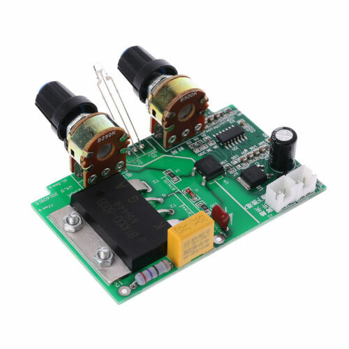
ABB painting robots need to exchange a large number of signals with the spray booth, air control unit, paint delivery system, high-voltage system, safety equipment, and production line PLC. After an anomaly occurs in the PSIB-02 board 3HNA010419-001 or related wiring, it may result in failure to meet process conditions, inaction of peripheral equipment, or interruption of the painting program.
On-site diagnostic conclusion: Loss of painting signals is not necessarily due to damage of the PSIB-02 board. Anomalies in the 24V control power supply, connectors, peripheral sensors, PLC program, I/O mapping, and communication modules can all cause the same phenomenon. Before repair, the fault location should be determined based on the scope of missing signals, whether it is a single channel, an entire group of interfaces, or the common part of the board.
1. Confirm the board and control cabinet model
Check the complete material number and hardware version on the board to confirm it is PSIB-02 3HNA010419-001. Simultaneously record the IRC5P control cabinet model, robot model, and painting system configuration. Connection methods may differ for different control cabinets and process systems; interfaces should be verified against electrical drawings before replacement.
2. Main function of the PSIB-02 board
PSIB-02 is one of the interface boards in the painting control system, used to connect the robot controller with some process or peripheral signals. Its related signals may involve equipment enable, process start, status feedback, and interlock conditions. The specific terminals and signal definitions should be based on the corresponding painting system drawings.
3. Common fault manifestations
Common phenomena include the painting program waiting for a signal, peripheral equipment failing to start, all I/O in a certain group having no status, failure to meet high-voltage or air control conditions, the robot's automatic program stopping midway, and signals being intermittent. Some faults only appear when the control cabinet temperature rises or the equipment vibrates.
4. Record alarms and missing signals
Before inspection, save the complete alarm content, program stop position, missing signal names, and I/O addresses. Simultaneously record the robot operating mode and peripheral equipment status. If only one input or output is abnormal, focus on checking the corresponding channel; if an entire group of signals is lost simultaneously, prioritize checking the common power supply, connectors, and board.
5. Check the control power supply
Measure the control power supply for the PSIB-02 board and related I/O circuits, observing whether the voltage is stable when the control cabinet starts and peripheral equipment operates. If the voltage drops significantly after a certain valve group, relay, or actuator is energized, check whether the downstream load is short-circuited, overloaded, or has poor line contact.
6. Check fuses and protection circuits
Confirm that the fuses, circuit breakers, and electronic protection in the board and peripheral power supply circuits are in normal condition. If a fuse is found blown, first check the load and cables; do not simply replace the fuse and re-energize. A persistent short circuit may cause damage again to the interface board's output channels or common power supply circuit.
7. Check connectors and terminals
Check whether the PSIB-02 board connectors are fully inserted, the locks are intact, and if there are bent pins, retracted pins, oxidation, liquid ingress, or burn marks on the terminals. Oil mist, solvents, and dust in the painting environment can easily cause poor contact. If the fault changes with vibration or pressing on the plug, focus on checking the connectors and solder joints.
8. Check input signals
For input signals such as sensors, pressure switches, equipment enable, and status feedback, check step by step starting from the field device. Confirm that the sensor itself operates normally, the power supply is stable, the line is conductive, and observe whether the status changes at the board end to determine if the fault lies in the field device, cable, or input channel.
9. Check output signals
If the controller screen shows the output is energized, but the valve group, relay, or peripheral equipment does not operate, check the board output, external power supply, and load wiring. The output channel may be damaged due to a short circuit or overload, or the external relay coil, valve coil, or connection terminals may be faulty.
10. Check PLC and communication status
The painting system typically coordinates the robot and peripheral equipment via a PLC or communication network. If multiple signals are abnormal simultaneously, check the PLC operating status, fieldbus, communication modules, and network connections. I/O loss caused by communication interruption cannot be resolved by replacing the PSIB-02 board; first determine whether the signal is hardwired or transmitted over the network.
11. Check I/O mapping and system configuration
After system recovery, software upgrades, or controller replacement, I/O mapping, device names, and signal addresses may have changed. If the field wiring and board are both normal, but the program cannot read the corresponding status, verify the controller configuration, PLC addresses, and signal names used in the robot program.
12. Check safety and process interlocks
When conditions such as spray booth ventilation, safety doors, fire protection, air pressure, paint supply, and high-voltage enable are not met, the system will prohibit the painting process from starting. Check the interlock status item by item according to the process start sequence to confirm whether the signal has not reached the PSIB-02 board or the control program has not output the enable command.
13. Check the PSIB-02 board itself
After confirming the power supply, connectors, peripheral equipment, and system configuration are normal, then check the PSIB-02 board itself. Focus on observing whether there is burning, corrosion, component cracking, relay discoloration, loose solder joints, or signs of liquid ingress. If localized blackening appears near a certain channel, also check the external load connected to that channel.
14. Analyze intermittent signal faults
Intermittent faults are commonly seen with loose connectors, cracked solder joints, internal wire breaks in sensor cables, and decreased thermal stability of electronic components. Record the control cabinet temperature, robot posture, peripheral equipment actions, and program steps when the fault occurs, seeking conditions that can stably reproduce the fault.
15. Precautions for board replacement
Before replacement, verify the complete material number 3HNA010419-001, hardware version, and control cabinet configuration. Take photos of all plug positions and make markings before disassembly. Before installing the new board, external short circuits and overloads must be eliminated to avoid damaging the new board again. After replacement, also check if the system requires re-confirmation of device or I/O configuration.
16. Functional verification after repair
After powering on, first check the board power supply, indicator status, and controller alarms, then test each related input and output signal one by one. Subsequently, perform linkage tests according to the normal start sequence of air, paint, high voltage, and the robot program, confirming that each process enable and feedback signal can be transmitted stably.
17. Summary
When a fault occurs with the ABB IRC5P painting control cabinet PSIB-02 board 3HNA010419-001, troubleshooting should follow the sequence of control power supply, fuse protection, connectors, inputs/outputs, PLC communication, I/O mapping, and the board itself. After repair is completed, verify all process signals, safety interlocks, and the painting program, confirming the system can stably complete production cycles before resuming automatic operation.
Repair Consultation
If you need to handle ABB IRC5P painting control cabinet PSIB-02 board 3HNA010419-001 faults, process signal loss, or peripheral interlock anomalies, please provide the robot model, control cabinet model, complete alarm screenshots, missing signal names, board photos, and wiring photos.
Industrial Robot Repair Hotline: +86 18122009539
Contact Repair Engineer: +86 18122009539