
ABB IRB 5500 Painting Robot ACU-01 Air Control Unit 3HNA013719-001 Fault Repair: Troubleshooting Air Pressure and Atomization Abnormalities
When a fault occurs in the ABB IRB 5500 painting robot's ACU-01 air control unit 3HNA013719-001, it may cause issues such as inability to establish air pressure, atomizer failure to start, unstable spray pattern, or painting program interruption. This article introduces troubleshooting methods for the air supply, filters, solenoid valves, pressure feedback, control signals, and the ACU-01 unit itself.
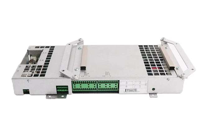
ABB painting robots require a stable air supply from the air control system for the atomizer, shaping air, and related pneumatic components. After an abnormality occurs in the ACU-01 air control unit 3HNA013719-001 or the peripheral air circuits, it may cause the atomizer to fail to start, abnormal pressure feedback, spray pattern changes, and painting program interruption.
On-site diagnostic conclusion: When air pressure or atomization alarms appear, the ACU-01 should not be directly judged as damaged. Insufficient workshop air supply pressure, clogged filters, air hose leaks, missing control signals, abnormal pressure sensors, and internal faults in the atomizer can all produce similar phenomena. Inspection should be performed step-by-step following the airflow and signal direction.
1. Confirm the complete model of the air control unit
Check the unit nameplate and part number to confirm it is ACU-01 3HNA013719-001. Simultaneously record the robot model, painting control cabinet type, atomizer model, and air circuit configuration. This component may be used in different S4P+ or IRC5P painting systems; specific interfaces and air circuit functions should be based on the equipment drawings.
2. Main functions of the ACU-01
The ACU-01 is used to control specific air circuits within the painting system, regulating or switching the corresponding air paths based on control commands. Different configurations may involve atomizer drive air, shaping air, bearing protection air, or pneumatic valve control. The actual channel functions should be confirmed based on the air circuit diagram and system parameters.
3. Common fault manifestations
Common phenomena include inability to establish pressure, significant deviation between set value and feedback value, atomizer failure to start, sudden pressure drop during operation, unstable spray pattern, and noticeably increased air consumption. Some faults only appear when multiple air circuits operate simultaneously, the robot reaches a specific position, or after continuous operation for a period of time.
4. Record alarms and pressure data
Before inspection, complete alarm information, pressure set values, actual feedback values, atomizer status, and robot program position should be recorded. Simultaneously confirm whether the fault occurs during air supply connection, atomizer startup, or stable painting phase. Comparing with normal equipment or historical data helps determine which air circuit the abnormality is concentrated in.
5. Check the workshop air supply
First, confirm the workshop compressed air supply is stable, and the main line pressure and flow rate can meet the painting system's operational requirements. If the fault worsens when multiple devices use air simultaneously, the air compressor, air receiver tank, main pipeline, and air supply capacity should be checked. Insufficient air supply should not be misdiagnosed as an ACU-01 fault.
6. Check air filtration and drying
Moisture, oil, and impurities in the compressed air can clog valve bodies, damage seals, and affect pressure sensors. Filters, oil-water separators, and drying devices should be checked. Accumulated water should be drained promptly, and clogged filter elements replaced. If significant moisture or oil is found inside the air hoses, the upstream air treatment system should also be checked.
7. Check the supply air piping
Check the ACU-01 inlet hose, outlet hose, fittings, and seals for looseness, cracking, or air leaks. Leak locations can be judged by combining airflow sounds and pressure holding status. If pressure still drops rapidly after closing the control valve, downstream hoses, the atomizer, and actuators should be further checked.
8. Check solenoid valve operation
Confirm the controller has issued the opening command for the corresponding air circuit, and observe whether the solenoid valve can normally energize and de-energize. If there is a control signal but the valve body does not actuate, check the coil power supply, connector, coil condition, and whether the valve spool is stuck. After long-term exposure to moisture and paint contamination, the valve body may exhibit slow action or inability to close completely.
9. Check the pressure sensor
Abnormal pressure sensors may cause the actual air pressure to be normal, but the controller displays pressure that is too low, too high, or fluctuating. Compare an independent pressure gauge reading with the control system feedback value, and check the sensor power supply, signal wires, and connectors. If a fixed deviation exists, it may be necessary to check the sensor zero point, range, or signal processing circuit.
10. Check control signals and I/O
If the ACU-01 does not receive the air opening or adjustment command, check the robot program, PLC interlock, I/O mapping, and interface board status. When conditions such as safety doors, spray booth ventilation, high voltage enable, or other process conditions are not met, the control system may also actively prohibit the startup of related air circuits.
11. Check the atomizer
If the ACU-01 output is normal but the atomizer still cannot start, check the atomizer's internal air passages, bearings, turbine, cup head, and related valves. Paint or cleaning solvent entering the air passages may cause increased resistance and abnormal rotational speed. Do not compensate for internal mechanical faults in the atomizer by continuously increasing air pressure.
12. Check connectors and wiring harnesses
Check the ACU-01 electrical connectors, valve coil plugs, and pressure sensor wiring for looseness, oxidation, liquid ingress, or broken wires. Oil mist and solvents in the painting environment may enter connectors, causing intermittent loss of control or feedback signals.
13. Check the ACU-01 unit itself
After confirming the air supply, hoses, control commands, and pressure feedback are normal, then check the ACU-01 unit itself. Focus on checking whether the valve body is contaminated, seals are aged, internal air passages are clogged, solenoid valves are stuck, and whether electrical components show corrosion, burning, or loose solder joints.
14. Why pressure may fluctuate repeatedly
Pressure fluctuations may originate from insufficient upstream air supply capacity, degraded pressure regulator performance, unstable solenoid valve operation, sensor feedback drift, or intermittent hose leaks. If fluctuations are synchronized with specific program steps, check the corresponding air circuit and control commands. If all air circuits fluctuate simultaneously, prioritize checking the common air supply and the common parts of the ACU-01.
15. Precautions for replacing the air control unit
Before replacement, verify the complete part number 3HNA013719-001, interface type, and air circuit configuration. Before disassembly, photograph all hose and plug positions and make clear markings. During installation, ensure hoses are connected correctly, seals are reliable, and no impurities are inside. Simultaneously confirm electrical connectors and grounding are restored correctly.
16. Functional verification after repair
After restoring air supply and power, first check static pressure and pipeline leaks, then test the opening, closing, and pressure feedback of each related air circuit individually. Subsequently, run the painting program at low speed, observing whether air pressure remains stable in different robot postures. Finally, use process test pieces to verify atomization effect, spray pattern, and coating quality.
17. Summary
When a fault occurs in the ABB IRB 5500 painting robot's ACU-01 air control unit 3HNA013719-001, troubleshooting should follow the order of workshop air supply, air filtration, supply piping, solenoid valves, pressure sensors, control signals, and the unit itself. After repair completion, verification of air pressure stability, atomizer operation, and actual painting quality is required. Confirm the system can complete continuous production cycles before resuming automatic operation.
Repair Consultation
If you need to handle faults with the ABB IRB 5500 painting robot's ACU-01 air control unit 3HNA013719-001, air pressure abnormalities, or atomizer failure to start, please provide the robot model, control cabinet model, complete alarm screenshots, pressure data, photos of the air control unit, and fault videos.
Industrial Robot Repair Hotline: +86 18122009539
Contact Repair Engineer: +86 18122009539