
ABB Painting Robot 3HNA011999-001 High-Voltage Board Fault Repair: Troubleshooting High Voltage Failure to Establish and Frequent Tripping
When the ABB painting robot 3HNA011999-001 high-voltage board malfunctions, it may cause electrostatic high voltage failure to establish, immediate tripping after startup, unstable high-voltage output, or decreased paint transfer efficiency. This article introduces troubleshooting methods for safety interlocks, control power supply, high-voltage generation unit, atomizer, grounding, and the high-voltage board itself.
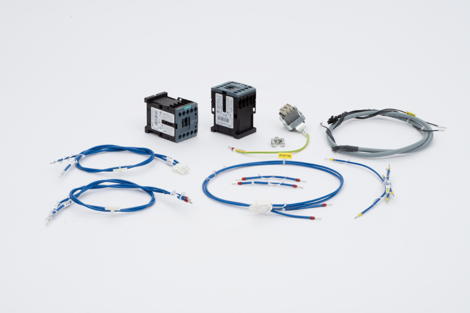
ABB painting robots form a complete electrostatic painting system consisting of high-voltage control, atomizer, air control, paint delivery, grounding, and safety interlocks. After anomalies occur in the 3HNA011999-001 high-voltage board or related circuits, issues such as high voltage failing to start, disconnecting immediately after establishment, output fluctuations, or decreased painting effectiveness may arise.
On-site diagnostic conclusion: A high-voltage alarm does not necessarily indicate damage to the 3HNA011999-001 high-voltage board. Atomizer contamination, high-voltage cable leakage, poor workpiece grounding, unmet safety interlock conditions, and abnormal peripheral loads can all cause the system to actively cut off the high voltage. External conditions should be checked first before testing the high-voltage board.
1. Confirm the complete model of the high-voltage board
Check the board's nameplate and part number to confirm it is 3HNA011999-001, while also recording the painting robot model, IRC5P control cabinet configuration, high-voltage generation system, and atomizer model. Interfaces and control methods may differ between painting systems; hardware versions and connectors must be verified before replacement.
2. Composition of the high-voltage control system
The electrostatic painting high-voltage chain typically includes control commands, safety interlocks, high-voltage control board, high-voltage generation unit, high-voltage cable, atomizer electrode, and workpiece grounding. An anomaly in any link can cause high voltage failure to establish; therefore, checks should proceed step-by-step along the signal path.
3. Common fault manifestations
Common phenomena include no output after the high-voltage start command is issued, immediate tripping after high voltage is established, repeated output interruptions during painting, unstable high-voltage values, and decreased paint transfer efficiency on workpieces. Some faults only appear when painting specific colors, when the robot reaches specific positions, or after the equipment has run for a period.
4. Record alarms and process status
Before inspection, complete alarm information, high-voltage setpoint, feedback value, painting program, robot position, and fault occurrence time should be recorded, while confirming the startup sequence for air, paint, atomization, and high voltage. Alarm history can help determine whether the fault occurs during the high-voltage enable, voltage rise, or stable output phase.
5. Check safety interlocks
The painting system typically requires conditions like spray booth ventilation, access control, fire protection, grounding, air pressure, and peripheral equipment status to be met before high voltage is allowed to start. If any safety interlock is not satisfied, the control system will prohibit or cut off the high voltage. Safety status and PLC interlock signals should be confirmed first; do not misdiagnose an interlock fault as high-voltage board damage.
6. Check control power supply
Check whether the power supply for the 3HNA011999-001 high-voltage board and related control circuits is stable, and whether connection terminals are loose, oxidized, or burnt. If the power supply drops at the moment of high-voltage startup, investigate whether the power module, fuse protection, wiring contacts, or downstream loads have short circuits or overloads.
7. Check high-voltage start command
Confirm that the robot program or painting control system has issued the high-voltage enable and setpoint commands, and check whether the high-voltage board receives the corresponding signals. If the input commands do not arrive, continue checking the PLC, process control board, communication module, and I/O mapping; do not directly repair the high-voltage board.
8. Check high-voltage feedback signals
The high-voltage system typically returns voltage, current, or operating status to the controller. If the setpoint signal is normal but the feedback remains zero, it may be related to the high-voltage generation unit, feedback wiring, or the board's detection circuit. If the feedback becomes abnormal quickly after voltage rise, check for leakage, grounding, and atomizer contamination.
9. Check atomizer and electrode
After paint, cleaning agents, or moisture adhere to the atomizer surface, a high-voltage leakage path may form, causing the system to fail to raise voltage or trip frequently. Check whether the cup head, electrode, insulating components, and mounting position are clean, dry, and intact, while observing for cracks, carbonization, or discharge traces.
10. Check high-voltage cable
When high-voltage cable insulation ages, gets crushed, surface becomes contaminated, or connectors loosen, partial discharge and current anomalies may occur. If faults only occur when the robot moves to specific postures, focus on checking flexible cables and bending points, ensuring cables do not rub against the robot body or spray booth structure.
11. Check workpiece and equipment grounding
Electrostatic painting requires a stable grounding circuit. Paint buildup on workpiece hangers, conveyor chain contamination, loose ground wires, or increased contact resistance can all affect high-voltage stability and paint transfer efficiency. Check the grounding connections between the robot, spray booth, atomizer system, conveying equipment, and workpieces.
12. Check high-voltage board connectors
Check whether the 3HNA011999-001 board connectors are fully seated, and whether terminals have bent pins, retracted pins, oxidation, liquid ingress, or burning. Oil mist and solvents in the painting environment may enter connectors and cause poor contact. If faults vary with vibration or temperature changes, focus on checking plugs and solder joints.
13. Check high-voltage board itself
After confirming external power supply, commands, atomizer, high-voltage cable, and grounding are normal, then check the high-voltage board. Focus on observing whether the circuit board has burning, corrosion, component cracking, insulation degradation, relay abnormalities, or loose solder joints. If carbonization or discharge traces are found, also investigate external causes of overvoltage or leakage.
14. Distinguish between high-voltage board and high-voltage generation unit faults
If control commands and board output status are normal but high voltage still cannot be established, continue checking the high-voltage generation unit and its load. If the fault persists after replacing with a compatible high-voltage board, the problem usually lies with the cable, atomizer, grounding, generation unit, or system configuration. Replacement testing must use parts with matching models and versions.
15. Repair and replacement precautions
Before disassembly, save painting parameters and photograph all connector positions. Cut off power according to equipment requirements and confirm the high-voltage circuit is fully discharged. After repair, perform power supply, insulation, control signal, and output status checks. Before installing a new board, external short circuits, leakage, and grounding anomalies must be eliminated to avoid re-damage.
16. High-voltage verification after repair
During the first startup, begin with lower process conditions, observe whether high-voltage setpoint, feedback, and operating status are stable, then gradually restore normal parameters. Subsequently, run the painting program at low speed without load, check whether high voltage interrupts at different robot postures, and finally use process samples to verify spray pattern, paint transfer efficiency, and coating quality.
17. Summary
When the ABB painting robot 3HNA011999-001 high-voltage board malfunctions, troubleshoot in the order of safety interlocks, control power supply, high-voltage commands, feedback signals, atomizer, high-voltage cable, grounding, and the board itself. After repair or replacement, verification of high-voltage stability, robot trajectory, and actual painting quality is required; confirm the system will not trip again before resuming production.
Repair Consultation
If you need to address ABB painting robot 3HNA011999-001 high-voltage board faults, high voltage failure to establish, or frequent tripping during painting, please provide the robot model, IRC5P control cabinet model, complete alarm screen photos, high-voltage board photos, atomizer model, and fault videos.
Industrial Robot Repair Hotline: +86 18122009539
Contact Repair Engineer: +86 18122009539