
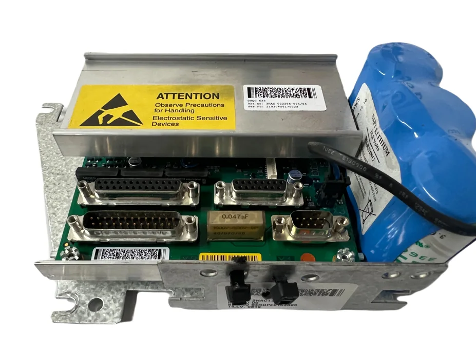
ABB Robot DSQC633 SMB Board Fault Repair: Troubleshooting Lost Revolution Counters, Battery Alarms, and Position Anomalies
The ABB IRC5 robot uses the SMB (Serial Measurement Board) to collect position feedback from each axis motor and stores data related to the revolution counters. When the DSQC633 SMB board, backup battery, robot arm cable, or connectors malfunction, it can lead to lost revolution counters, abnormal position data, the robot being unable to enable, or program point offsets. This article introduces the functions of the DSQC633, fault diagnosis, line inspection, data recovery, and machine restart verification methods.
In this article
ABB IRB 6640 Robot Counterbalance Cylinder Oil Leak Repair: Troubleshooting Abnormal Load, Abnormal Noise, and Seal Failure on Axis 2
ABB IRB 6640 is a heavy-duty six-axis industrial robot commonly used for material handling, spot welding, casting, and large workpiece operations. The robot's Axis 2 needs to withstand the combined torque generated by the upper arm, forearm, wrist, tool, and workpiece. The counterbalance device helps reduce the continuous load on the Axis 2 servo motor in different postures.
When the counterbalance cylinder experiences seal aging, rod wear, loose connections, or internal abnormalities, the robot may exhibit oil leaks, abnormal noise, unsteady motion, increased Axis 2 current, and following errors.
On-site Judgment Conclusion:
When oil traces appear on the surface of the counterbalance cylinder, first clean and confirm the actual leak location, then inspect the seals, piston rod, connecting pins, and the mechanical condition of Axis 2. Do not simply wipe off the oil and continue operation, nor disassemble the counterbalance device without supporting the robot arm.
Scope of Application:
This article primarily applies to ABB IRB 6640 series robots configured with the IRC5 control system. Counterbalance devices for different load capacities, arm spans, and hardware versions may vary. Specific structures, part numbers, disassembly/assembly methods, and technical data should be based on the robot nameplate and the corresponding ABB maintenance manual.
1. Role of the Counterbalance Cylinder in the IRB 6640
Robot Axis 2 drives the entire arm to swing back and forth, requiring it to withstand significant gravitational torque in certain postures.
The main functions of the counterbalance device include:
- Reducing the continuous load on the Axis 2 servo motor.
- Decreasing the torque required for robot upper arm movement.
- Improving Axis 2 acceleration and deceleration performance.
- Reducing motor and drive temperature rise.
- Enhancing stability during heavy-duty motion.
- Reducing energy consumption in static robot postures.
If the counterbalance force decreases, the Axis 2 motor needs to output greater torque to maintain the same motion, potentially causing abnormal current, temperature, and motion states.
2. Common Symptoms of Counterbalance Cylinder Failure
When the IRB 6640 counterbalance device malfunctions, the following may be observed on-site:
- Oil traces appearing on the surface of the counterbalance cylinder.
- Continuous oil seepage near the piston rod.
- Oil leakage at the cylinder end or seams.
- Friction or impact sounds during Axis 2 movement.
- Unsteady motion of the robot upper arm.
- Significant load difference when Axis 2 moves upward versus downward.
- Increased temperature of the Axis 2 motor.
- Sinking or rebound when the robot stops.
- IRC5 controller displaying Axis 2 overload or following errors.
- Clearance appearing at the connection points of the counterbalance device.
Counterbalance cylinder failure typically affects Axis 2, but not all Axis 2 abnormalities originate from the counterbalance cylinder. The reducer, servo motor, brake, and tool load should also be checked simultaneously.
3. Information to Record Before Repair
Before starting inspection, record:
- Complete robot model and load version.
- Robot body serial number.
- IRC5 controller model.
- RobotWare software version.
- Complete part number of the counterbalance device.
- Leak location and extent of oil traces.
- Robot posture corresponding to the fault.
- Axis 2 movement direction and speed.
- Tool and workpiece load data.
- Axis 2 alarm codes and alarm text.
- Date of last maintenance and repair.
- Whether the robot has experienced any collisions.
It is recommended to first photograph the oil traces, cylinder body, piston rod, connection points, and overall robot posture for comparison after cleaning to identify the leak location.
4. How to Confirm a Genuine Leak
After long-term operation, the counterbalance cylinder surface may accumulate reducer oil, grease, or external production media. Do not judge cylinder leakage based solely on surface oil traces.
Inspect in the following order:
Step 1: Record the original location and extent of the oil traces.
Step 2: Use appropriate cleaning agents to remove surface oil and dirt.
Step 3: Check if other leakage sources exist, such as from the reducer, lubrication ports, or surrounding components.
Step 4: Operate Axis 2 at low speed under safe conditions.
Step 5: Observe if oil traces reappear at the piston rod, seal port, end cap, or seams.
Step 6: Record the speed at which oil traces appear and the robot posture.
If oil traces reappear from the piston rod seal area after cleaning, focus on inspecting the seal and piston rod surface. If oil traces appear from fixed seams or connection ports, inspect the corresponding sealing surfaces and fastening condition.
5. Piston Rod and Seal Fault Inspection
The surface condition of the counterbalance cylinder piston rod directly affects sealing performance.
Focus on checking:
- Whether scratches exist on the piston rod surface.
- Presence of corrosion, pits, or attached foreign objects.
- Signs of uneven wear on the surface.
- Whether the seal port continuously carries out oil.
- Whether dust protection components are damaged.
- Whether the piston rod exhibits deflection during movement.
If only the seal is replaced without addressing piston rod scratches, the new seal may fail again in a short time.
Seal failure can also be caused by long-term eccentric loads, misaligned assembly, contaminant ingress, or material aging. Therefore, during repair, also check the connection and guiding condition.
6. Counterbalance Device Connection Point Inspection
The counterbalance device connects to the robot body via pins, bushings, or mounting brackets. Wear or looseness at connection points can cause abnormal noise and motion impact.
Inspection includes:
- Whether mounting bolts are loose.
- Whether pins and bushings are worn.
- Whether retaining rings and anti-loosening components are intact.
- Whether mounting brackets show cracks or deformation.
- Whether abnormal clearance exists at connection points.
- Whether interference occurs during robot movement.
If clear impact sounds occur during Axis 2 reversal, but the counterbalance cylinder body shows no obvious leakage, focus on checking pin, bushing, and mounting bracket clearance.
7. How to Distinguish Between Counterbalance Cylinder and Axis 2 Reducer Abnormal Noise
Both the counterbalance cylinder and Axis 2 reducer can produce abnormal sounds during Axis 2 movement.
Common characteristics of counterbalance device abnormal noise:
- Sound originates near the cylinder body or connecting pins.
- Impact sounds occur during Axis 2 reversal.
- Friction sounds appear during piston rod extension/retraction.
- There is a noticeable difference in sound when moving in different directions.
- Abnormal gaps can be observed at connection points.
Common characteristics of abnormal noise in Axis 2 reducer:
- The sound originates from inside the Axis 2 joint.
- The abnormal noise occurs at fixed mechanical cycles.
- The sound significantly increases at certain angles.
- It is accompanied by mechanical backlash or positioning deviation.
- There is oil leakage or temperature rise near the reducer.
Sound localization can be performed by operating at low speeds, in different directions, and at different angles. Do not confirm the fault by repeatedly running at high speeds.
8. Judgment of Axis 2 current and load changes
After the balancing force decreases, Axis 2 typically requires greater motor torque when lifting the arm.
On-site comparisons can be made:
- Axis 2 load status before and after repair under the same program.
- Differences when Axis 2 moves upward and downward.
- Differences between no-load and loaded states.
- Load variations under different robot postures.
- Whether the Axis 2 motor temperature continues to rise.
- Whether alarms occur during acceleration or deceleration phases.
If the load during upward movement of Axis 2 increases significantly, while the state during downward movement is different, check whether the balancing device provides normal auxiliary force, and simultaneously rule out tool load and mechanical interference.
The load or current trend displayed by the controller can only serve as auxiliary judgment and cannot replace mechanical inspection.
9. Tool load parameters can also affect judgment
Incorrect tool weight, center of gravity, and inertia parameters can also cause increased Axis 2 current or following error.
Inspection items include:
- Whether the actual tool weight has changed.
- Whether the workpiece weight exceeds the original setting.
- Whether the tool center of gravity is correct.
- Whether accessories have been added to the gripper.
- Whether tool cables and air hoses are pulling on the arm.
- Whether the load data used in the controller is correct.
If Axis 2 load abnormalities appear only after changing the tool, first confirm the load parameters and external interference before judging the state of the balancing cylinder.
10. Judgment directions for IRC5 alarms
【Overload occurs during upward movement of Axis 2】
Priority checks: balancing device, tool load, mechanical resistance, and Axis 2 motor.
【Following error occurs during Axis 2 reversal】
Priority checks: balancing cylinder connection gap, Axis 2 reducer backlash, and encoder feedback.
【Alarm occurs after Axis 2 runs for a period of time】
Priority checks: motor temperature rise, mechanical resistance, balancing capability, and control cabinet cooling.
【Abnormal noise occurs at fixed postures】
Priority checks: piston rod position, connecting pins, Axis 2 reducer, and external interference.
【Upper arm sinks after robot stops】
Priority checks: brake, balancing device, and Axis 2 mechanical transmission.
【Multiple axes alarm simultaneously】
Priority checks: control cabinet common power supply, drive system, and safety status, rather than only checking the balancing cylinder.
11. Safety requirements before disassembling the balancing cylinder
The arm and end effector of the IRB 6640 are relatively heavy. After removing the balancing device, Axis 2 may lose its original supporting force.
Before disassembly:
- Move the robot to the maintenance posture specified in the manual.
- Use mechanical supports and lifting devices that meet requirements.
- Stop the robot operation.
- Cut off relevant energy sources.
- Perform lockout and tagout.
- Confirm that Axis 2 will not rotate on its own.
- Remove or secure the end effector and load.
- Mark the installation direction and connection positions of the balancing device.
Do not rely solely on the servo motor brake to support the robot arm. The disassembly and assembly process should be performed by maintenance personnel with relevant experience.
12. Professional maintenance content for the balancing cylinder
After confirming a fault in the balancing cylinder body, maintenance typically includes:
- Cylinder body appearance and dimensional inspection.
- Piston rod surface inspection.
- Seal and dust seal inspection.
- Internal guide and moving parts inspection.
- Connection ends and mounting hole inspection.
- Pin and bushing wear inspection.
- Cylinder body cleaning and contaminant handling.
- Seal replacement and assembly.
- Post-maintenance sealing and motion testing.
The specific internal structure, working medium, and inspection requirements should be based on the technical documentation of that balancing device.
13. Balancing cylinder maintenance process
Step 1: Record robot posture, oil traces, and alarm information.
Step 2: Verify the complete material numbers of the robot and balancing device.
Step 3: Clean the surface and confirm the actual leakage location.
Step 4: Inspect the piston rod, seal ports, and connection areas.
Step 5: Inspect the Axis 2 reducer, motor, and tool load.
Step 6: Move the robot to the specified maintenance posture.
Step 7: Use mechanical devices to reliably support the robot arm.
Step 8: Disassemble and inspect the balancing device.
Step 9: Repair or replace confirmed damaged components.
Step 10: Restore the balancing device according to its original installation position.
Step 11: Complete Axis 2 low-speed, loaded, and process verification.
14. Key inspection points after installation
After the balancing cylinder installation is complete, confirm:
- Correct installation direction.
- Clean mounting base and positioning surfaces.
- Complete installation of bolts, pins, and anti-loosening components.
- Normal piston rod movement direction.
- No mechanical interference at connection points.
- Correct routing of external cables and hoses.
- No continued leakage at the cylinder body and seal locations.
- Normal Axis 2 mechanical zero point and calibration status.
- Correct tool and workpiece load parameters.
Before removing the mechanical support from the robot arm, re-check all connection components.
15. Post-maintenance restart verification
After completing maintenance, perform in sequence:
- Check that no tools or foreign objects are left in the maintenance area.
- Confirm that protective devices and connectors are restored to normal.
- Check Axis 2 calibration and position data.
- Perform low-speed operation of Axis 2 upward and downward movements.
- Observe whether the balancing cylinder extension and retraction are smooth.
- Check whether oil traces reappear at seal ports and the cylinder body.
- Listen for abnormal noise at connecting pins and the Axis 2 joint.
- Check the temperature rise of the Axis 2 motor and balancing device.
- Execute a no-load multi-axis coordinated motion program.
- Perform low-speed loaded testing after restoring the tool.
- Gradually restore to normal production speed.
- Use process samples to verify positioning and production quality.
It is recommended to recheck the surface of the balance cylinder after the first restart to confirm the seal condition is stable.
16. Common Issues
Does a small amount of oil stain on the balance cylinder surface require immediate replacement?
First clean and confirm the source of the oil stain. If it continues to appear from the seal area after cleaning, arrange for further inspection.
Can oil seepage from the balance cylinder cause Axis 2 alarms?
After leakage leads to a decrease in balancing capability, the load on the Axis 2 motor may increase, potentially causing overload, temperature rise, or following error.
Does the robot need recalibration after repairing the balance cylinder?
It depends on the scope of disassembly and whether the mechanical position has changed. After repair, confirm the Axis 2 calibration status, TCP, and program reference points.
Can the balance cylinder be directly removed and sent for repair?
Arm support cannot be ignored. Before disassembly, the robot must be placed in the specified posture, and reliable support or lifting equipment must be used.
17. Daily Maintenance Recommendations
- Regularly check the balance cylinder surface for oil seepage.
- Observe whether the piston rod is scratched or corroded.
- Check the pin shaft, bushings, and mounting bolts.
- Record Axis 2 temperature and changes in operating sound.
- Update load data after tool changes.
- Check the balancing device and Axis 2 after a robot collision.
- Clean promptly and continue observing after discovering leakage.
- Do not continue high-speed operation under load after abnormal noise or increased leakage.
18. Summary
When oil seepage, abnormal noise, or unsteady movement occurs in the ABB IRB 6640 balance cylinder, first confirm the leakage location, then check the seal, piston rod, pin shaft, bushings, and mounting base.
If the fault is accompanied by Axis 2 overload, temperature rise, or following error, also check the tool load, Axis 2 reducer, servo motor, brake, and encoder feedback.
Technical content reference: ABB IRB 6640 robot mechanical structure, IRC5 control system technical documentation, and industrial robot field repair experience
Content update time: September 2026
Repair Consultation
If repair is needed for the ABB IRB 6640 robot balance cylinder, Axis 2 reducer, or servo system, please provide the robot's complete model, body serial number, balancing device nameplate, photos of the leakage location, alarm information, and operation video.
Industrial Robot Repair Hotline: +86 18122009539
Contact Repair Engineer: +86 18122009539
Need a part or repair assessment?
Share the robot model, part number, fault details and destination country with our team.
Contact our team ↗