
ABB Robot Control Cabinet Common Fault Troubleshooting: Power-On Failure, Drive Alarms, and Overheating Investigation
The ABB robot control cabinet is responsible for system power supply, motion control, communication, and safety management. After prolonged operation, issues such as failure to power on, servo enable failure, drive module alarms, communication interruptions, and excessive internal cabinet temperature may occur. This article introduces common faults in ABB robot control cabinets, on-site diagnostic methods, repair procedures, and key points for restart verification.
In this article
ABB Robot Controller Common Fault Troubleshooting: Failure to Start, Drive Alarms, and Overheating Inspection
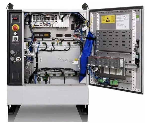
ABB robot controller cabinets typically include the main power supply, control power supply, main computer, drive modules, axis computers, safety modules, communication modules, and cooling systems. When any one of these components malfunctions, the robot may experience failure to power on, servo enable failure, unexpected stops during operation, or communication interruptions.
Controller cabinet faults involve power supply, software, communication, and external safety circuits. One should not directly conclude a module is damaged based on a single alarm code. Before repair, alarm records should be saved, and troubleshooting should be performed step by step, considering the fault occurrence time, indicator light status, and robot operating conditions.
1. Common Fault Manifestations in ABB Robot Controller Cabinets
Common on-site faults include:
- The controller cabinet completely fails to power up.
- Power indicator lights are on, but the system fails to start.
- The teach pendant screen is black or cannot connect to the controller.
- The system is stuck on the startup screen.
- The robot servo cannot be enabled.
- Drive modules display overcurrent, overheating, or communication alarms.
- Sudden stops during automatic operation.
- Abnormal noise from the controller cabinet fans or fans stop rotating.
- Frequent alarms after running for a period of time.
- The controller cabinet temporarily recovers after a restart but fails again subsequently.
- Burnt smell, dust accumulation, oil contamination, or noticeable heat inside the controller cabinet.
Different fault phenomena correspond to different inspection directions. Complete lack of power should first check the power input; if it can start but cannot enable, then check the safety circuit, drive system, and related alarms.
2. Information to Record Before Repair
Before starting inspection, it is recommended to record:
- Robot model and serial number.
- Controller cabinet model.
- RobotWare or system version.
- Alarm code, alarm text, and occurrence time.
- Whether the teach pendant can normally enter the system.
- Indicator light status of each module in the controller cabinet.
- Whether the fault occurred during power-up, enable, or operation phase.
- The axis number corresponding to the fault.
- Whether there have been recent power outages, collisions, or part replacements.
- Whether the controller cabinet interior has ever been exposed to moisture, dust, or oil.
- Whether the device programs, parameters, and system backups are complete.
If the controller can still enter the system, first back up the programs, system parameters, and important configurations. Backup files should note the device name and date, and confirm they can be read normally.
3. How to Troubleshoot Controller Cabinet Failure to Power Up
If the controller cabinet has no indicator lights, and the fans and teach pendant show no response, start checking from the external power supply.
【External Power Supply Abnormality】
Check the controller cabinet incoming power lines, isolation switches, circuit breakers, and related protective devices. Confirm the input voltage and phase sequence meet equipment requirements.
【Internal Power Supply Protection Activation】
Short circuits, overloads, or module faults may cause circuit breakers, fuses, or power supply protection to activate. After a protective device activates, do not directly replace it and repeatedly power on; first identify the cause.
【Power Module Fault】
When the control power module is abnormal, the controller cabinet may have main power input, but the main computer, teach pendant, and control circuits cannot function normally.
【Cable or Terminal Abnormality】
Loose incoming line terminals, poor connector contact, and burnt cables may cause the controller cabinet to have no power or intermittent power loss.
Before inspecting inside the controller cabinet, first disconnect the main power supply and complete lockout/tagout. The controller cabinet may contain energy storage components; wait for the specified discharge time according to the equipment manual.
4. Power On But System Fails to Start
If the controller cabinet indicator lights are on, but the teach pendant cannot enter the system, check the control power supply, main computer, and system startup components.
Possible causes include:
- Unstable control power supply output.
- Main computer module abnormality.
- Internal storage media or system file abnormality.
- Loose motherboard connectors.
- Communication abnormality between modules.
- Abnormal power loss to the controller cabinet causing startup failure.
- Internal temperature too high or circuit board moisture exposure.
If the system is stuck on a fixed startup screen, record the screen content and the indicator light status of each module. Do not continuously force power-off restarts to avoid further damage to data or storage media.
5. Teach Pendant Cannot Connect to Controller Cabinet
A black teach pendant screen or communication interruption is not necessarily due to damage to the teach pendant itself; it may also be caused by controller cabinet interface or power supply abnormalities.
Key inspection points include:
- Teach pendant cables and connectors.
- Controller cabinet teach pendant interface.
- Teach pendant supply voltage.
- Main computer startup status.
- Internal communication modules and lines.
- Whether connector pins are bent, oxidized, or retracted.
If conditions permit, use a confirmed normal and model-matched teach pendant for verification. If the fault persists after replacement, continue checking the controller cabinet interface, power supply, and main computer.
6. Troubleshooting Directions for Servo Unable to Enable
When the controller can start normally but the robot cannot enable, first check the current alarms; do not directly replace the drive module.
【Safety Circuit Not Satisfied】
Emergency stop button not reset, safety door open, safety relay abnormality, or missing external safety signals can all prevent servo enable.
【Drive Module Alarm】
Drive overcurrent, overheating, power supply abnormality, or communication fault will cause the system to prohibit motor operation.
【Motor or Power Cable Fault】
Motor winding abnormality, power cable short circuit, and connector burning may trigger drive protection.
【Encoder Feedback Abnormality】
Encoder, feedback cable, or connector faults affect position feedback, preventing normal servo startup.
【Mechanical Load Abnormality】
Brake not released, reducer jam, or external tooling interference may also cause alarms during enable or motion phases.
During troubleshooting, based on the alarm's corresponding axis number and occurrence conditions, gradually determine whether the issue lies with the controller cabinet, cables, motor, or mechanical body.
7. How to Judge Drive Module Alarms
ABB controller cabinet drive systems may experience faults such as overcurrent, overvoltage, undervoltage, overheating, and communication abnormalities.
【Alarm Immediately Upon Power-Up or Enable】
Prioritize checking the drive module, motor power lines, and servo motor.
【Alarm During High-Speed or Heavy-Load Operation】
Prioritize checking load parameters, mechanical resistance, motor, and drive heat dissipation.
【Alarm When Reaching a Fixed Position】
Prioritize checking body cables, external cables, and mechanical interference.
【Alarm After Running for a Period of Time】
Prioritize checking the control cabinet fan, filter cotton, internal cabinet temperature, and module temperature rise.
The same alarm may be caused by multiple components. Before replacing a drive module, possibilities such as power cable short circuits, motor abnormalities, and excessive mechanical load should be ruled out.
8. How to Handle Excessive Control Cabinet Temperature
Abnormal heat dissipation in the control cabinet affects the stable operation of the power supply, main computer, and drive modules.
Common causes include:
Filter cotton clogged with dust and oil contamination.
Air intake or exhaust vents blocked.
Cooling fan stopped rotating.
Fan speed decreased or bearing abnormal noise.
Control cabinet door not properly closed.
Air conditioner or heat exchange device failure.
Ambient temperature too high.
Severe dust accumulation inside the control cabinet.
During maintenance, check the fan rotation direction, airflow, filter cotton, and ventilation path. After cleaning, also observe whether the module temperature returns to normal.
If the equipment only alarms after continuous operation for several hours, record the time from startup to alarm and compare performance in cold and hot states.
9. Common Causes of Communication Abnormalities
ABB robot control cabinets may need to communicate with teach pendants, I/O devices, PLCs, fieldbuses, and external axes. Communication failures can cause signal loss, inability to start programs, or robot stoppage.
Inspection items include:
Whether communication cables are loose or damaged.
Whether connectors are locked.
Whether communication module indicator lights are normal.
Whether network addresses and related configurations have been modified.
Whether external devices are powered on normally.
Whether shielding and grounding are reliable.
Whether the fault occurred after equipment modification or parameter adjustment.
If communication abnormalities only appear during robot motion, check the robot body cables and external moving cables. If multiple devices in the entire network go offline simultaneously, check switching equipment, power supply, and main communication lines.
10. Common Faulty Components Inside the Control Cabinet
Common maintenance targets in the control cabinet include:
Main computer module.
Control power supply module.
Drive module.
Rectification and power distribution components.
Axis computer board.
Safety board.
I/O board.
Communication module.
Fans and filtration devices.
Connectors, terminals, and internal cables.
Fault detection should combine the module name, complete material number, and hardware version. Modules with similar appearances may have differences in power, interfaces, or software compatibility; do not select spare parts based solely on appearance.
11. Common Maintenance Misconceptions
Immediately replacing a module upon seeing a module alarm.
Repeatedly resetting alarms without saving records.
Running with the control cabinet door open when overheating occurs.
Restoring power directly after a protective device trips.
Replacing main computer components without backing up programs and parameters.
Installing replacement modules without verifying the complete material number.
Not checking the safety circuit after maintenance.
Only performing power-on tests without verification under load operation.
Opening the control cabinet door may disrupt the original heat dissipation path and increase the risk of dust, oil contamination, and foreign objects entering; it should not be used as a long-term cooling method.
12. ABB Control Cabinet Maintenance Process
Step 1: Record the Fault
Save the alarm code, occurrence time, module indicator light status, and on-site photos.
Step 2: Back Up Data
Back up programs, parameters, and system configuration if the system permits.
Step 3: Perform Safe Shutdown
Disconnect relevant power supplies, perform lockout/tagout, and wait for energy storage components to discharge.
Step 4: Perform Visual Inspection
Check modules, fans, filter cotton, wiring terminals, and connectors.
Step 5: Check Power Supply
Confirm the status of input power and all levels of control power.
Step 6: Narrow Down the Fault Range
Based on the alarm occurrence phase, separately check the safety circuit, main computer, drives, motors, cables, and mechanical load.
Step 7: Repair or Replace Components
Verify the module material number, version, installation location, and connection method.
Step 8: Restore and Verify
Check wiring, system parameters, safety functions, and robot operating status.
13. Post-Maintenance Restart Verification
After control cabinet maintenance, complete the following in sequence:
Confirm no tools or foreign objects are left inside.
Check that all modules and connectors are securely installed.
Confirm the control cabinet door, protective panels, and grounding are restored to normal.
Power on and observe indicator lights, fans, sounds, and odors.
Confirm the system can start normally.
View current and historical alarms.
Test emergency stop, safety door, and enable functions.
Run each axis separately at low speed.
Perform no-load trajectory testing.
Gradually restore speed and actual load.
Check control cabinet temperature and the operating status of each module.
Use process samples to confirm positioning and production quality.
Record the fault cause, maintenance content, and verification results.
14. Summary
When an ABB robot control cabinet experiences failure to start, drive alarms, or excessive temperature, troubleshoot in the order of "external power supply—control power—main computer—safety circuit—drive system—motor and cables—mechanical load."
A control cabinet alarm does not necessarily indicate the module itself is damaged. Poor heat dissipation, loose connectors, motor short circuits, and mechanical jamming can all trigger control system protection. By saving alarm information, verifying spare part models, and completing restart verification, misjudgments and repeated downtime can be reduced.
Maintenance Consultation
If ABB robot control cabinet maintenance is required, please provide the robot model, controller model, system version, alarm code, complete material number of the faulty module, as well as control cabinet indicator light status and photos or videos of the fault scene, and contact a maintenance engineer for further diagnosis.
Industrial Robot Maintenance Hotline: +86 18122009539
Contact Maintenance Engineer: +86 18122009539
Need a part or repair assessment?
Share the robot model, part number, fault details and destination country with our team.
Contact our team ↗