
ABB Teach Pendant Repair for Cable Connection Faults
Diagnose ABB teach pendant disconnections by checking fault records, cable condition, connectors, controller interfaces, and configuration compatibility.
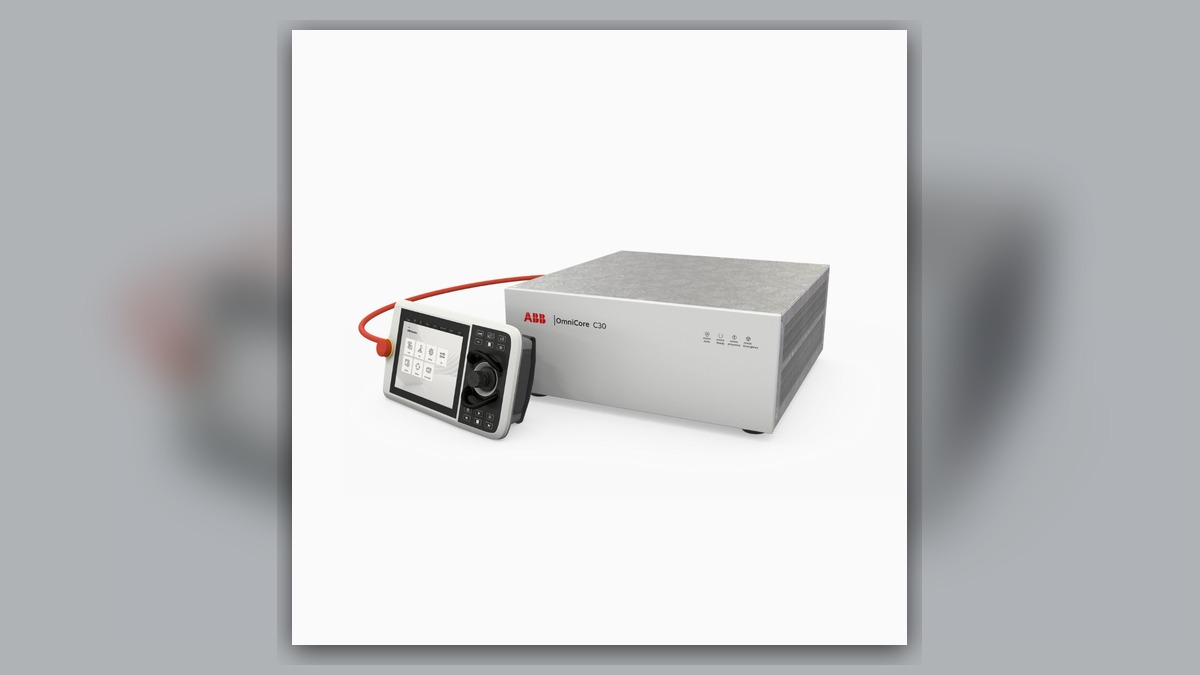
ABB teach pendant repair for a connection fault should begin by recording the complete message, controller state, and conditions immediately before communication was lost. Potentially involved systems include the pendant cable, connectors, controller interface, emergency-stop circuit, pendant electronics, and installed configuration. A blank display, frozen interface, or disconnected-pendant message does not independently prove that the pendant is defective. Cable movement, connector damage, controller faults, and incompatible replacement hardware can produce similar symptoms and must be separated before repair or replacement.
Symptoms and Equipment Scope
This diagnostic approach applies to ABB robot systems equipped with a wired teach pendant, including relevant IRC5 systems using an ABB FlexPendant. Exact interfaces, connector arrangements, software support, and approved connection procedures depend on the installed controller and pendant generation. Confirm the applicable ABB product documentation before disconnecting or exchanging hardware.
Connection-related symptoms may include a pendant that starts and then disconnects, a display that changes when the cable is moved, loss of operator input, or failure of the controller to recognize the pendant. A consistently blank display can also involve power delivery or internal electronics, so it should not automatically be classified as a communication problem.
Information to Record First
Preserve the available evidence before resetting or cycling controller power. Repeated resets can remove useful context without correcting the underlying fault.
Complete alarm code and full text:
Date and exact time:
Faulted axis:
Robot position/posture:
Program step or motion:
Actual speed and load condition:
Reset result:
Time until recurrence:
Related power, communication or feedback alarms:
For a pendant connection fault, also record whether the display remained illuminated, whether inputs stopped responding, and whether the symptom appeared after cabinet work, pendant replacement, cable movement, or an impact. Identify the robot model, controller model, pendant part number, hardware revision, and connector layout.
Safety and Preparation
Place the robot in a safe state according to the site procedure and applicable ABB operating information. Only suitably competent personnel should inspect controller and pendant connections. Do not bypass the emergency-stop circuit, defeat enabling-device functions, open energized equipment, or repeatedly move a visibly damaged cable to reproduce an intermittent fault.
Before handling connectors, follow the required shutdown and isolation procedure. Inspect only accessible areas unless the work is assigned to personnel qualified for controller service. A teach pendant is part of the operator and safety interface; normal screen operation alone does not verify all safety functions.
ABB Teach Pendant Repair Diagnostic Sequence
1. Confirm the complete symptom. Determine whether the pendant is completely unpowered, powered but frozen, intermittently disconnected, or recognized with only certain controls unavailable. These states lead to different diagnostic branches. Record any earlier controller event because the final visible message may be a consequence rather than the initiating fault.
- Verify equipment identity. Compare the pendant label with the controller model and installed system configuration. If a replacement or borrowed unit was recently fitted, match the exact part number, hardware revision, cable arrangement, and applicable software support. Physical connector fit alone does not establish compatibility.
- Inspect the external cable. With the system safely isolated, examine the full accessible cable length, strain reliefs, outer jacket, and areas repeatedly bent during operation. Look for crushing, cuts, sharp bends, contamination, loose strain reliefs, or evidence of pulling. Visible damage supports cable inspection or professional testing, but the absence of external damage does not prove that internal conductors are intact.
- Inspect accessible connectors. Check for incomplete seating, damaged locking features, contamination, bent or recessed contacts, and signs of mechanical stress. Use the connection procedure for the exact controller configuration. Do not apply unverified pinout information or probe contacts while energized.
- Review when the fault occurs. A fault associated with a repeatable cable position may indicate a cable or termination problem, but controlled observation should be performed only when permitted by ABB instructions and site safety rules. Do not keep flexing a suspect cable merely to trigger the failure. A fault unrelated to cable position may require evaluation of pendant electronics, controller interfaces, power delivery, or configuration.
- Separate the pendant from the controller side. Where approved compatible equipment and a safe substitution procedure are available, qualified personnel may use a known-serviceable assembly to help isolate the fault. Change only one item at a time and retain the original event records. If the symptom remains with a verified compatible pendant and cable, investigate the controller interface and configuration rather than assuming that both pendants are defective.
When Repair or Replacement May Be Considered
Professional inspection is appropriate when the cable has intermittent continuity, a connector is mechanically damaged, liquid has entered the enclosure, or the pendant remains unstable after external connections and compatibility have been checked. Internal assessment may cover power conversion, communication circuitry, display connections, controls, and connector terminations, depending on the exact pendant version.
Repair should not be selected solely because the pendant was the last device handled. Replacement may be more suitable when damage cannot be restored reliably or the correct repair parts are unavailable. Any spare must match the exact model, part number, hardware revision, connector layout, and controller requirements.
For broader ABB robot repair support, see https://autonews.best/abb-robot-repair. If evidence points to the controller rather than the pendant, information about ABB IRC5 controller inspection and repair is available at https://autonews.best/products/abb-irc5-kong-zhi-gui-yu-ji-xiu. ZHB is an independent industrial robot inspection, repair, and maintenance service provider that also supplies parts to overseas customers; it does not imply ABB authorization.
Verification After Repair or Replacement
After reconnection, qualified personnel should confirm normal controller recognition, stable display operation, operator inputs, enabling-device behavior, and emergency-stop functionality in accordance with the applicable ABB instructions and site validation procedure. Review the event log for recurrence. If controlled movement is required, perform it at an appropriate reduced-risk stage under established safeguards; do not reproduce a hazardous motion merely to test the repair.
Information Required for a Repair Inquiry
Provide the robot model, controller model, complete alarm code and text, alarm history, pendant component label, fault conditions, and clear photographs of the pendant, cable damage, and connectors. Include whether the display remains powered, what actions preceded the disconnection, and whether any controller or pendant hardware was recently replaced.
Conclusion
An ABB pendant connection fault can originate in the cable, connectors, pendant electronics, controller interface, or configuration. Reliable ABB teach pendant repair depends on preserving fault evidence, confirming exact hardware identity, inspecting low-risk external points first, and isolating one subsystem at a time. The observed symptom should guide testing, not predetermine which component is replaced.