
Factory Robotics Repair and Maintenance Services Market: KUKA KR C4 Drive-Enable Triage
A practical KUKA KR C4 diagnostic intake process helps factories separate safety, power, connection, configuration, and drive-related faults.
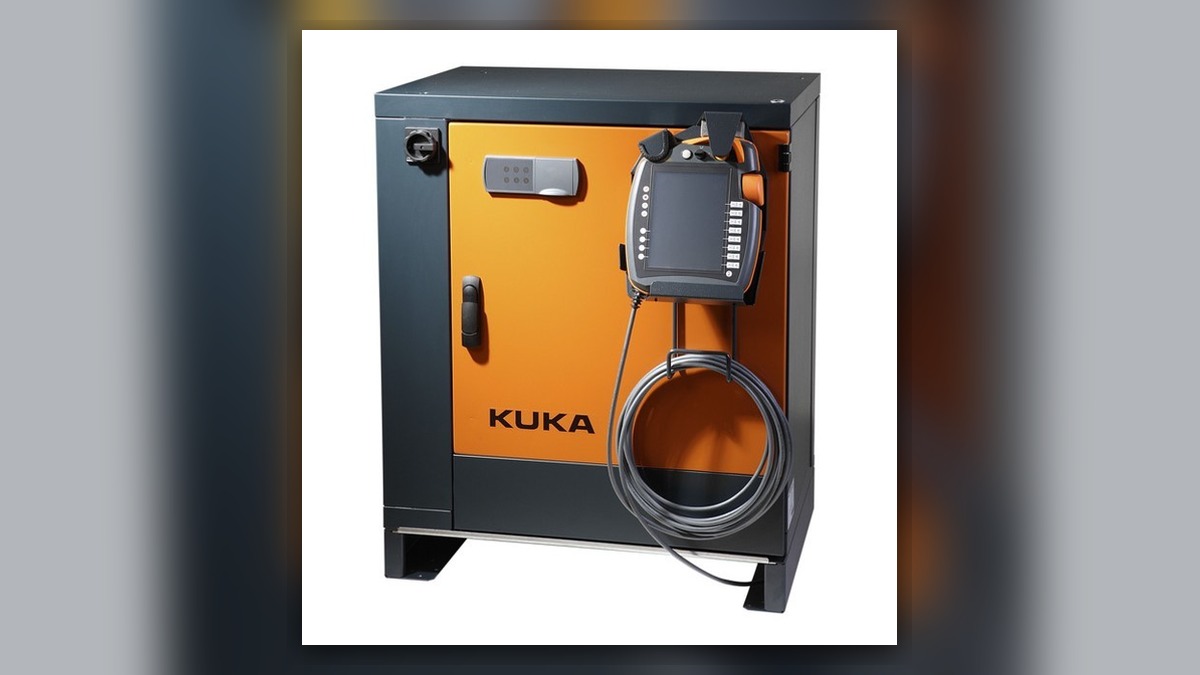
A KUKA robot that cannot enable its drives may involve the safety circuit, external interlocks, controller power, cabinet connections, system configuration, or a drive-related component. Within the factory robotics repair and maintenance services market, an effective repair request therefore begins with the complete message history, controller and robot identification, failure time, operating state, and recent work. A drive-enable symptom alone does not prove that a drive module is damaged, and replacing parts before the fault path is established can conceal the original cause.
Symptoms and Scope
This diagnostic scope applies to a KUKA robot using a KR C4 controller when the system powers up but drive enabling does not complete, motor power drops out, or motion remains unavailable. It does not cover a controller that is completely unpowered, a confirmed mechanical seizure, or a specific alarm requiring a separate manufacturer-defined procedure.
The operator may observe that the robot remains stopped after an enable request, that an external automatic-start sequence cannot proceed, or that drive availability changes intermittently. These observations establish the fault stage, but they do not independently identify a failed drive, motor, cable, safety device, or controller board.
Information to Record First
Capture the evidence before resetting the controller or disconnecting components. Alarm history can reveal whether the drive-enable symptom followed a safety, power, communication, or configuration event.
Complete alarm code and full text:
Date and exact time:
Faulted axis:
Robot position/posture:
Program step or motion:
Actual speed and load condition:
Reset result:
Time until recurrence:
Related power, communication or feedback alarms:
Also record the KUKA robot model, KR C4 controller variant, system software information shown by the controller, and the identification labels of any suspected component. Note whether the problem began after cabinet service, cable work, equipment relocation, backup restoration, collision recovery, facility maintenance, or a prolonged shutdown. These conditions guide the next inspection without confirming a cause.
Safety and Preparation
Follow the applicable KUKA operating information and the factoryâÂÂs lockout, electrical safety, and safeguarded-space procedures. Cabinet access and energized inspection must be limited to appropriately qualified personnel. Do not bypass an emergency-stop channel, gate circuit, enabling device, or external safety controller to obtain drive power.
Preserve current programs, configuration data, calibration information, and relevant logs before changes are made. Do not repeatedly request motion merely to reproduce an intermittent failure. Observation under motion, when genuinely necessary, should be performed only by suitably competent personnel under controlled conditions and according to the manufacturerâÂÂs instructions and site risk controls.
Diagnostic Sequence for a Drive-Enable Failure
- Establish the controller state. Determine whether the KR C4 completes startup and whether the pendant remains responsive. Record all active messages and the events immediately preceding the drive-enable failure. If an earlier message identifies a safety, communication, power, or configuration problem, investigate that message before treating the drive symptom as an independent drive fault.
- Confirm the operating request and external conditions. Identify the selected operating mode, the source of the enable request, and whether the cell is controlled locally or by an external automation system. Check the visible state of emergency-stop devices, access protection, enabling controls, and cell interlocks without bypassing them. If an external permission is absent, the next action is to inspect the relevant cell control and safety documentation rather than replace robot hardware.
- Review external power and recent interruptions. Confirm from approved facility indicators and maintenance records whether the controller received the specified supply and whether an instantaneous power interruption occurred around the recorded fault time. Any electrical measurement must use the method and conditions defined for the installed controller and must be performed by qualified personnel. A power event can explain loss of drive availability, but it does not by itself prove damage inside the controller.
- Inspect accessible connections and visible condition. With the equipment in the required safe state, inspect external controller cables, cabinet interfaces, grounding connections, and robot-side cable routing for looseness, contamination, impact, overheating evidence, or damaged locking features. Connector names and layouts vary with the installed KR C4 configuration, so identification should be verified against the correct documentation before anything is disconnected.
- Check configuration and service history. Compare the current hardware arrangement with the controller documentation and recent maintenance record. If the fault appeared after component replacement, backup restoration, or cable service, verify that the installed component, hardware revision, connector layout, and configuration are appropriate for that exact system. Do not change parameters simply to see whether the robot will start.
- Escalate to component-level evaluation only after upstream conditions are established. If safety permissions, external control signals, supply conditions, configuration, and connections are consistent with the required state, professional evaluation of the drive system may be appropriate. The inspection scope may include the relevant drive-related component and associated connections, but a repair or replacement decision should be based on documented testing rather than the enable symptom alone.
Factory Robotics Repair and Maintenance Services Market: Defining the Repair Scope
Technical buyers should distinguish among remote log review, on-site diagnosis, component repair, spare-part supply, preventive maintenance, and restart support. A quotation should identify the included equipment, evidence required, inspection boundaries, excluded site work, and verification criteria. This is more useful than comparing a single repair price without confirming whether the underlying safety, control, cabling, or drive cause has been isolated.
When a suspected part is sent for inspection, match its exact model, part number, hardware revision, and connector layout. Photographs of the complete label and connector side help prevent identification errors. Where broader industrial robot repair support is required, the service scope is available at https://autonews.best/services.
Verification After Repair or Replacement
After approved work is completed, restore guards and connections, confirm that no tools or temporary test equipment remain, and review the controller messages before requesting motion. Verify drive enabling first without assuming that the original cause has been removed. Then confirm the relevant operating modes, external interlocks, and program start conditions.
Any controlled motion check must follow the applicable KUKA instructions and site safety procedure. Begin with the minimum motion necessary to confirm function, monitor for recurrence, and retain the post-service alarm log. Do not use extended production operation as the first proof of repair. If the fault returns, preserve the new event sequence and compare it with the original record before further part substitution.
Common Diagnostic Mistakes
Frequent errors include clearing the event history before recording it, treating the last displayed message as the first cause, bypassing a safety condition, replacing a drive-related component without checking external permissions, and fitting a visually similar spare without verifying its full identification. Another mistake is combining several undocumented changes in one intervention, which makes the successful or unsuccessful result difficult to interpret.
Information Required for a Repair Inquiry
For one efficient repair inquiry, provide the robot model, KR C4 controller model, complete alarm code and text, alarm history, suspected component label, fault conditions, and clear photographs of the cabinet, component label, connectors, and visible damage. ZHB is an independent industrial robot inspection, repair, and maintenance service provider that also supplies parts to overseas customers. Details about recent service, power events, operating mode, reset behavior, and recurrence timing help determine whether remote review, on-site troubleshooting, or component inspection is the appropriate next step.
Conclusion
A KUKA KR C4 drive-enable failure should be diagnosed as a system-state problem before it is treated as a failed component. Preserve the complete event sequence, confirm safety and external permissions, review power and service history, inspect configuration-specific connections, and escalate to component testing only when the preceding conditions support it. This evidence-based scope allows factories and repair providers to make a defensible repair, replacement, and verification decision.