
KUKA Robot Repair: KR C4 Drive-Enable Troubleshooting
Use a model-specific sequence to investigate a KUKA KR C4 drive-enable fault, preserve alarm evidence, and avoid treating the symptom alone as proof of a failed component.
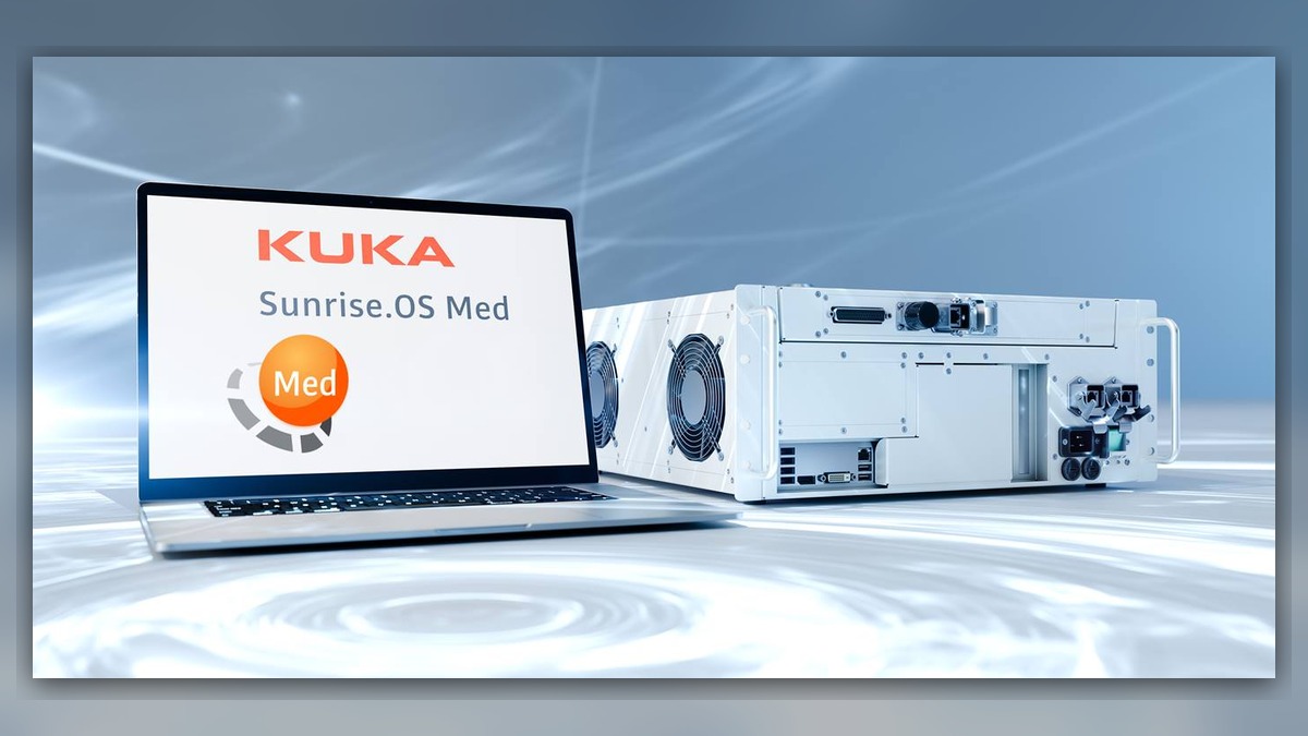
For KUKA KR C4 systems, a drive-enable problem can involve the controller, safety circuit, power supply, connections, configuration, or a drive component. The symptom alone does not identify which part has failed. Before diagnosis, record the complete message and event time, robot and controller identifiers, affected axis if shown, and the result of any reset. KUKA robot repair should begin by confirming the installed system and reviewing its event history; do not replace a drive or motor based only on a drive-enable symptom.
Symptoms and Scope
This guide addresses drive enable that is unavailable or drops out on a KUKA KR C4 system. It does not interpret a particular KUKA alarm code, cover every KR C4 configuration, or establish a diagnosis for other controller generations. Use the applicable KUKA documentation for the exact controller, robot, software version, and installed safety configuration. An error message, reset response, or indication that drives are not enabled cannot independently prove failure of a motor, cable, safety device, or drive module.
Information to Record First
Capture the complete alarm text or code exactly as displayed, including related messages and their order. Save the event history before clearing alarms where the installed system permits it. Record when the fault occurred, which axis or axes were affected, the robot position, the program step or operating state, and whether the event followed a change, maintenance activity, interruption, or restart. Note the outcome of a normal reset without repeatedly resetting the controller to force operation.
KUKA Robot Repair Diagnostic Sequence
- Confirm the equipment. Record the robot model, KR C4 controller identification, installed software information, and labels on any component suspected of involvement. Compare them with the plant equipment record and the matching KUKA documentation. If the controller generation or configuration does not match this guide, stop and use the applicable documentation instead of transferring KR C4 assumptions.
- Review the event sequence. Use the complete alarm history to identify the first relevant message, any simultaneous safety or power-related indications, and whether the symptom affects one axis or the whole robot. A preceding message may redirect diagnosis; a later drive-enable message may be a consequence rather than the initiating fault. Preserve the log and investigate in the order supported by the recorded events.
- Perform external, low-risk checks. With the equipment in a safe state under the site procedure, inspect accessible cabinet and robot connections for visible damage, looseness, contamination, or signs of overheating. Check external power and safety-circuit status only through approved indicators and procedures. Do not open energized equipment or disconnect components for exploratory testing. A visible defect warrants assessment of the affected connection or component; no visible defect does not rule out an electrical, configuration, or intermittent problem.
- Compare fault conditions. Determine whether the event is limited to one axis, occurs across multiple axes, or is associated with a particular operating condition using existing logs and permitted observations. A single-axis indication may help narrow the investigation, but does not by itself distinguish a drive, motor, feedback-related component, cable, or mechanical issue. A system-wide symptom may justify checking shared power and safety conditions, but does not prove that a shared component has failed. Any observation under motion must be performed only by competent personnel under controlled conditions and in accordance with KUKA operating information and site safety procedures. Do not repeat an action that could increase risk merely to reproduce the event.
- Escalate component testing. If the event history and approved checks point toward a specific circuit or component, have qualified personnel follow the exact model- and configuration-specific KUKA service procedure. Record what was inspected and the result before considering repair or replacement. When a part is proposed, verify its exact model, part number, hardware revision, and connector layout against the installed system. A matching label alone does not establish compatibility, and replacing one suspected part is not a confirmed remedy until the fault is diagnosed and verification is complete.
KUKA Robot Maintenance and Repair Records
For recurring or intermittent drive-enable events, retain a compact fault record with the details below. These details help distinguish a repeatable condition from incomplete evidence without presuming a cause.
Complete alarm code and full text:
Date and exact time:
Faulted axis:
Robot position/posture:
Program step or motion:
Actual speed and load condition:
Reset result:
Time until recurrence:
Related power, communication or feedback alarms:
Repair Inquiry Information
ZHB is an independent industrial robot inspection, repair and maintenance service provider that also supplies parts to overseas customers; this does not imply manufacturer authorization. For a repair inquiry, provide the robot model, controller model, complete alarm code and text, alarm history, component label, fault conditions, and clear photographs of the relevant equipment and visible connections. Include the recorded axis and operating conditions when available so the initial assessment can be matched to the installed system.
After Repair or Replacement
Before returning the robot to production, confirm that the work matches the applicable KUKA procedure and site safety requirements. Review the event history, check relevant connections and safety status through approved procedures, and confirm that the reported symptom is no longer present during authorized operation. Any post-repair operation under motion must be performed by competent personnel under controlled conditions; do not recreate a hazardous condition to test a repair. Document the parts and work performed, verification conditions, and any remaining alarms.
Conclusion
A KR C4 drive-enable symptom is a starting point for diagnosis, not proof of a failed component. Preserve the full event sequence, verify the exact robot and controller configuration, and use documented checks to distinguish system-level conditions from an axis-specific issue before repair or replacement.