
KUKA KR C2 Robot CI3 Safety Board 00-111-230 Fault Repair: Emergency Stop, Safety Door, and Drive Enable Failure
When a fault occurs in the KUKA KR C2 robot's CI3 safety board 00-111-230, it may cause the emergency stop state to be unresolvable, safety door signal abnormalities, drive enable failure, or sudden stops during robot operation. This article introduces the functions of the CI3 safety board, 24V power supply, KCP teach pendant, X11 external safety interface, and troubleshooting methods for dual-channel safety circuits.
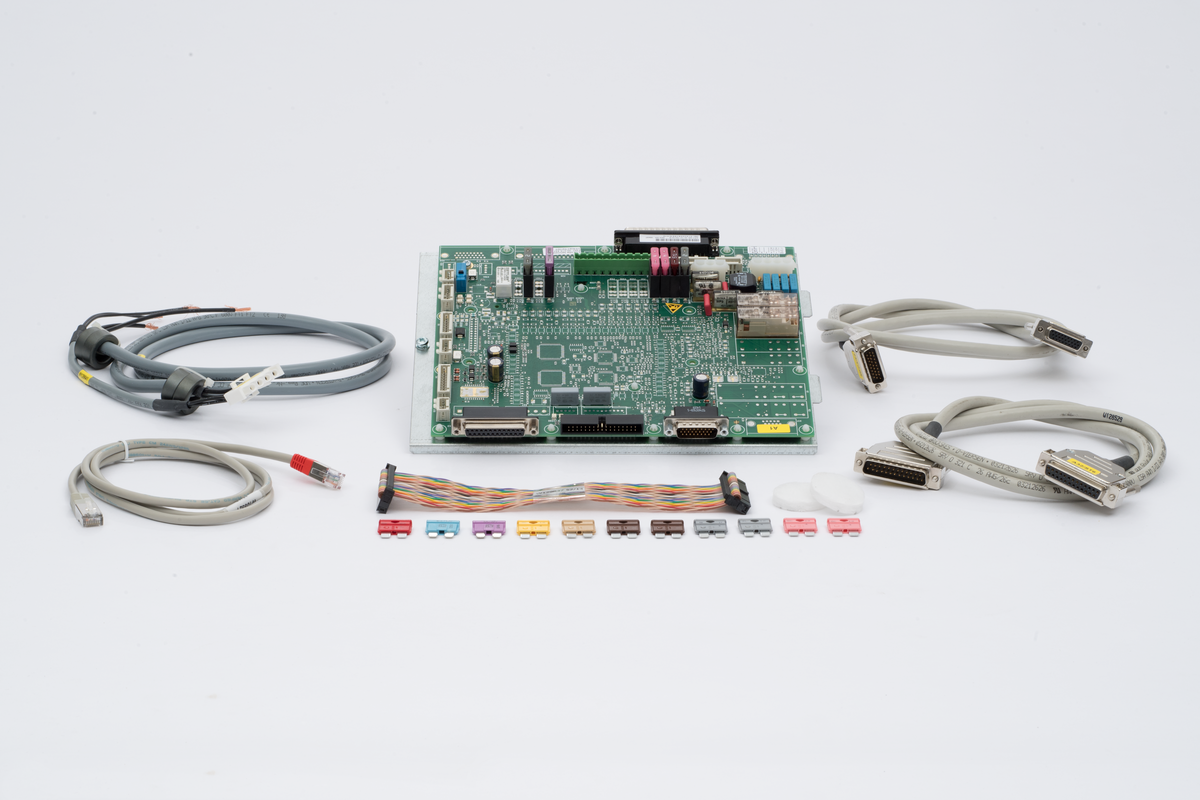
The emergency stop, safety door, KCP teach pendant enable switch, and external safety devices of the KUKA KR C2 robot need to form a complete safety chain. After an abnormality occurs in the CI3 safety board 00-111-230 or its peripheral circuits, the robot may remain in an emergency stop state, the drive may fail to engage, or it may stop suddenly during automatic operation.
On-site diagnostic conclusion: When a safety circuit alarm appears, the CI3 safety board should not be replaced directly. Similar faults can be caused by abnormalities in the KCP teach pendant, X11 external safety interface, 24V control power supply, safety relays, connecting cables, and peripheral safety PLCs. External signals should be confirmed first before judging the CI3 safety board itself.
1. Main Function of the CI3 Safety Board
The CI3 safety board is used to process some safety and interface signals within the KR C2 control cabinet, transmitting the status of emergency stops, safety doors, enables, and peripheral interlocks to the control system. Specific functions, interface locations, and signal definitions may vary with the KR C2 control cabinet version. Confirm based on the control cabinet nameplate, electrical drawings, and board version.
2. Common Fault Manifestations
CI3-related faults may manifest as: the KCP emergency stop is released but the system still shows emergency stop; the safety door status does not change after closing; the drive contactor cannot pull in; the robot cannot be enabled; and occasional safety stops during operation. Some faults may appear with changes in control cabinet temperature, vibration, or cable posture.
3. Record Complete Alarm Information
Before inspection, record the complete alarm content displayed on the KCP, the time of occurrence, operating mode, and robot status. Confirm whether the fault appears during control cabinet startup, drive engagement, manual operation, or automatic operation. Also check the alarm history to determine if the problem is persistent or intermittent.
4. Check the KCP Emergency Stop Button
Confirm the KCP teach pendant emergency stop button is fully released and the mechanical structure is not stuck. Then check if the emergency stop contacts can switch normally. After long-term bending or pulling of the KCP cable, internal safety wiring may break, causing the controller to continuously receive an emergency stop signal.
5. Check the Three-Position Enable Switch
In manual mode, the three-position enable switch on the back of the KCP needs to be held in the specified position. After switch contact wear, poor mechanical rebound, or internal wire breakage, the robot may not be manually enabled. During inspection, confirm that state changes when released, in the middle position, and fully pressed are normal.
6. Check the X11 External Safety Interface
The KR C2 control cabinet typically connects external emergency stops, safety doors, and peripheral safety devices through interfaces like X11. Loose external wiring, oxidized terminals, safety relays not reset, or safety PLCs not outputting a permit signal can all cause the drive to fail to engage. Check dual-channel safety signals item by item according to the corresponding control cabinet drawings.
7. Check the Safety Door and Peripheral Equipment
Confirm the safety door is closed and the door lock switch and dual-channel contacts can switch synchronously. If the robot is interlocked with conveyors, welders, turntables, or other equipment, also check if the peripheral equipment is in a state that permits robot operation. When an external emergency stop is not released, the CI3 safety board cannot complete a safety reset even if it is normal.
8. Check the 24V Control Power Supply
Measure the control power supply for the CI3 safety board and safety circuits, observing whether the voltage is stable during control cabinet startup, emergency stop release, and drive engagement. If the voltage drops at the moment of drive engagement, check the power module, fuses/protection, connection terminals, and external loads for short circuits or overloads.
9. Check Dual-Channel Signals
Emergency stops and safety doors typically use a dual-channel structure; the two signals need to change synchronously according to the specified state. If one channel is closed and the other is open, the control system will judge the safety circuit as abnormal. During troubleshooting, check the contacts, wiring, and input status of both channels separately; do not measure only one channel.
10. Check Connectors and Backplane
Check if the CI3 safety board connectors are firmly inserted and if pins are bent, retracted, oxidized, or burnt. Also observe if the fault state changes when the control cabinet vibrates. Poor contact between the board and backplane, loose connectors, or cracked solder joints may cause intermittent emergency stops and drive power loss.
11. Check Safety Relays and Contactors
Burnt, welded, or poorly rebounding contacts on safety relays may cause inconsistent dual-channel states. Abnormalities in drive contactor coils, auxiliary contacts, and connecting wiring can also manifest as drive engagement failure. For faults that appear after a period of operation, also check the temperature rise of relays, contactors, and terminals.
12. Check the CI3 Safety Board Itself
After confirming the KCP, external safety circuits, 24V power supply, and connectors are normal, then check the CI3 safety board. Focus on observing whether the circuit board shows signs of burning, corrosion, component cracking, relay discoloration, loose solder joints, or liquid ingress. Oil mist, metal dust, and moisture may cause leakage or poor contact on the board surface.
13. Why Faults May Appear Intermittently
Intermittent faults are common with internal wire breaks in KCP cables, loose X11 terminals, unstable relay contacts, poor board connector contact, and thermal expansion/contraction of solder joints. Record the control cabinet temperature, robot posture, peripheral equipment actions, and vibration conditions when the alarm occurs, seeking conditions that can stably reproduce the fault.
14. Precautions for Replacing the CI3 Safety Board
Before replacement, verify the complete material number 00-111-230, board version, interface type, and KR C2 control cabinet configuration. Before disassembly, photograph connector positions and make markings. During installation, check that connectors and the backplane are not damaged. Different version boards may look similar but their functions and interface configurations are not necessarily identical.
15. Safety Verification After Repair
After installing the board and powering on, first check system alarms and safety status. Then separately test the KCP emergency stop, control cabinet emergency stop, external emergency stop, safety door, and three-position enable switch. When each device is triggered, the robot should stop and display the corresponding status, and after release, it should reset according to the normal procedure.
16. Robot Recommissioning Test
After all safety functions are confirmed normal, test each axis movement in manual low-speed mode, then run a complete program at low speed with no load. After confirming the robot's trajectory is normal when passing near fixtures, workpieces, and peripheral equipment, gradually increase speed and proceed to production with load, while observing if safety stops or drive power loss reappears.
17. Summary
When a fault occurs in the KUKA KR C2 robot's CI3 safety board 00-111-230, first check the KCP emergency stop and enable switch, X11 external safety interface, dual-channel signals, 24V control power supply, safety relays, and connectors. Only after the entire peripheral safety chain is confirmed normal can you accurately determine if the CI3 safety board needs repair or replacement. After completing repairs, all safety functions must be verified item by item before resuming automatic operation.
Repair Consultation
If you need to handle KUKA KR C2 robot CI3 safety board 00-111-230 faults, emergency stop reset failure, safety door abnormalities, or drive enable failure, please provide the robot model, control cabinet nameplate, complete alarm screen photos, CI3 board photos, and X11 interface wiring photos.
Industrial Robot Repair Hotline: +86 18122009539
Contact Repair Engineer: +86 18122009539