
FANUC R-30iA Robot A06B-6117-H207 Dual-Axis Servo Amplifier Fault Repair
Introduces the inspection methods for the FANUC R-30iA control system A06B-6117-H207 dual-axis servo amplifier when multi-axis alarms, inability to enable, overcurrent, and overheating occur.
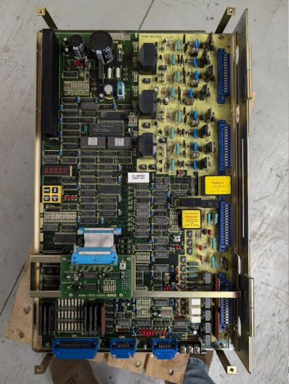
The A06B-6117-H207 is used for dual-axis servo drive in FANUC R-30iA related configurations. When two associated axes are abnormal simultaneously, priority should be given to checking the amplifier's common power supply, control signals, and module status, rather than replacing the two motors separately.
The key to on-site judgment is to first determine the fault scope, then decide on the repair target. During the inspection process, alarms, axis numbers, robot posture, and recurrence conditions should be recorded to avoid replacing components based solely on a single alarm.
- Common Fault Manifestations
- Two related axes simultaneously unable to enable
- Alarm occurs immediately after amplifier power-on
- Overcurrent, overload, or temperature abnormalities during robot operation
- Communication interruption between the controller and servo module
- Possible Causes
- Three-phase input or DC bus abnormality
- Short circuit in one of the two axis motors or power cables
- Poor heat dissipation in the control cabinet
- Mechanical axis jamming causing continuous overload
- Damage to the amplifier's internal power module or control board
- On-site Troubleshooting Sequence
- Record the alarm sequence of the two faulty axes to determine if it is a common fault.
- Check input power, fuses, contactors, and busbar connections.
- Separately check the two axis motors, power cables, encoder cables, and brakes.
- Check fans, heat sinks, and control cabinet ambient temperature.
- After confirming the external circuits are normal, perform testing on the amplifier or replace it with an identical version.
- Verification Before Replacing Components
Verify the complete suffix of A06B-6117-H207, controlled axes, capacity, R-30iA controller configuration, and connector positions. Mark the corresponding axes before disconnecting wires.
Similar appearance of models does not mean they can be directly replaced. Before procurement, provide the complete equipment model number, original component nameplate, interface photos, controller model, and alarm information.
- Post-Repair Restart Verification
After replacement, test each axis separately at low speed, then perform multi-axis coordinated motion and rated load operation. Confirm axis number correspondence, motion direction, zero point, and temperature rise are normal.
After repair completion, also save the test results, replacement component part numbers, and final parameters to facilitate tracking by subsequent maintenance personnel.
- Summary
When handling such faults, troubleshooting should follow the sequence of alarm records, power supply and connections, feedback circuits, mechanical load, and the component itself. Only after external conditions are confirmed normal can further judgment be made on whether the target component needs repair or replacement.
Industrial Robot Repair Hotline: +86 18122009539
Contact Repair Engineer: +86 18122009539