
How to Troubleshoot FANUC Robot Servo Amplifier Alarms? On-site Repair Approach for A06B-6127-H208
When a FANUC robot experiences issues such as servo enable failure, single-axis stop, operation jitter, or drive module alarms, troubleshooting should be conducted step-by-step, covering power supply, motor cables, encoder, mechanical load, and the servo amplifier.
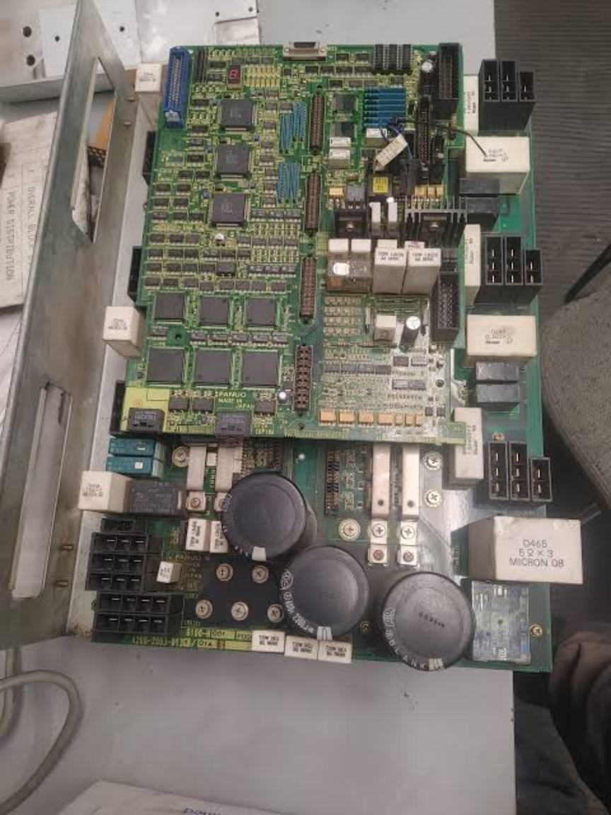
The A06B-6127-H208 is a servo drive module within the FANUC control system. When a robot experiences servo enable failure, single-axis stop, or positioning abnormalities, the fault may originate from the amplifier itself, or it could be caused by the motor, cables, encoder, or mechanical load.
The key to on-site diagnosis is first determining the scope of the fault before deciding on the repair target. During the inspection process, record alarms, axis numbers, robot posture, and recurrence conditions to avoid replacing components based solely on a single alarm.
- Common Fault Manifestations
- Servo cannot be enabled, alarm persists after reset.
- Single-axis stop, jitter, or increased positioning deviation.
- Amplifier displays overcurrent, overload, overheating, or communication abnormalities.
- Fault varies with robot posture, speed, or control cabinet temperature.
- Possible Causes
- Abnormal main circuit or control power supply.
- Short circuit in motor power cable, burnt connectors, or insulation degradation.
- Poor contact in encoder or feedback cable connections.
- Reducer jamming, external interference, or incorrect load settings.
- Abnormalities in the amplifier's internal power devices, fan, or control circuitry.
- On-site Troubleshooting Sequence
- Record the controller model, complete alarm message, faulty axis number, and the action during which the fault occurred.
- Measure the main circuit and control power supply; check fuses, contactors, and terminals.
- Check the control cabinet fan, filter screen, and amplifier heat dissipation path.
- Inspect motor power cables, feedback cables, brake, and mechanical load.
- Only after external issues are ruled out, proceed to inspect or replace the A06B-6127-H208.
- Verification Before Replacing Components
Before replacement, verify the complete model number, suffix, capacity, number of controlled axes, connector layout, and hardware version. Also, save system parameters and robot zero point data.
Similar external appearance does not guarantee direct interchangeability. Before procurement, provide the equipment's complete model number, the original component's nameplate, interface photos, controller model, and alarm information.
- Post-repair Verification and Commissioning
First, confirm the alarm is cleared. Then perform low-speed single-axis tests, low-speed coordinated motion tests, no-load continuous operation tests, and actual load tests, while monitoring motor and amplifier temperatures.
After repair is complete, also save the inspection results, replaced component part numbers, and final parameters to facilitate tracking for subsequent maintenance personnel.
- Summary
When handling such faults, follow the troubleshooting sequence: alarm recording, power supply and connections, feedback lines, mechanical load, and finally the component itself. Only after confirming external conditions are normal should you proceed to determine whether the target component requires repair or replacement.
Industrial Robot Repair Hotline: +86 18122009539
Contact Repair Engineer: +86 18122009539