
FANUC A20B-2101-0355 Servo Control Board Fault Repair: Troubleshooting Startup, Interface, and Signal Abnormalities
When a FANUC A20B-2101-0355 servo control side board experiences issues such as the board not being recognized, no interface output, or abnormal drive control, the first step is to verify the power supply, connections, and the associated main unit.
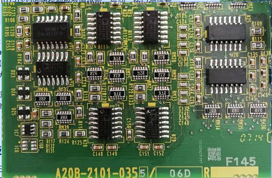
The A20B-2101-0355 is a FANUC servo control-related board. Board abnormalities may manifest as system startup failure, abnormal servo control, no interface output, or intermittent alarms.
The key to on-site diagnosis is first determining the fault scope, then deciding on the repair target. During inspection, record alarms, axis numbers, robot posture, and recurrence conditions to avoid replacing components based solely on a single alarm.
- Common Fault Manifestations
- Board not recognized after system power-up
- Abnormal servo control signals or detection signals
- Intermittent stoppage after the equipment has been running for a period of time
- Burn marks, corrosion, or component/connector damage on the board interface
- Possible Causes
- Abnormal board power supply voltage
- Poor connection between the side board and the main unit
- Connector oxidation, bent pins, or liquid ingress
- Decreased thermal stability of components or cracked solder joints
- Faults in the associated drive unit, motor, or external wiring
- On-site Troubleshooting Sequence
- Record the equipment model, control system, and alarm history.
- Check the board's power supply, interfaces, and mounting condition.
- Visually inspect the circuit board for burn marks, corrosion, and cracked components.
- Check the associated main unit, drive, and external signal lines.
- Only after confirming the peripherals are normal, proceed with board testing, repair, or replacement.
- Verification Before Replacing Components
Verify the complete A20B number, hardware version, installation location, main unit model, and interface layout. Avoid selecting a similar-looking board based solely on appearance.
Similar appearance does not guarantee direct interchangeability. Before procurement, provide the complete equipment model, original component nameplate, interface photos, controller model, and alarm information.
- Post-Repair Commissioning Verification
After replacement, check system startup, board recognition, servo enable, low-speed axis movement, and actual program operation. Also review the alarm history.
After repair completion, save the test results, replacement part number, and final parameters to facilitate tracking by subsequent maintenance personnel.
- Summary
When handling such faults, follow the troubleshooting sequence: alarm records, power supply and connections, feedback lines, mechanical load, and finally the component itself. Only after external conditions are confirmed normal can you further determine if the target component requires repair or replacement.
Industrial Robot Repair Hotline: +86 18122009539
Contact Repair Engineer: +86 18122009539