
FANUC R-30iB Robot SRVO-021 SRDY OFF Alarm Repair: Servo Amplifier and Motor Circuit Troubleshooting
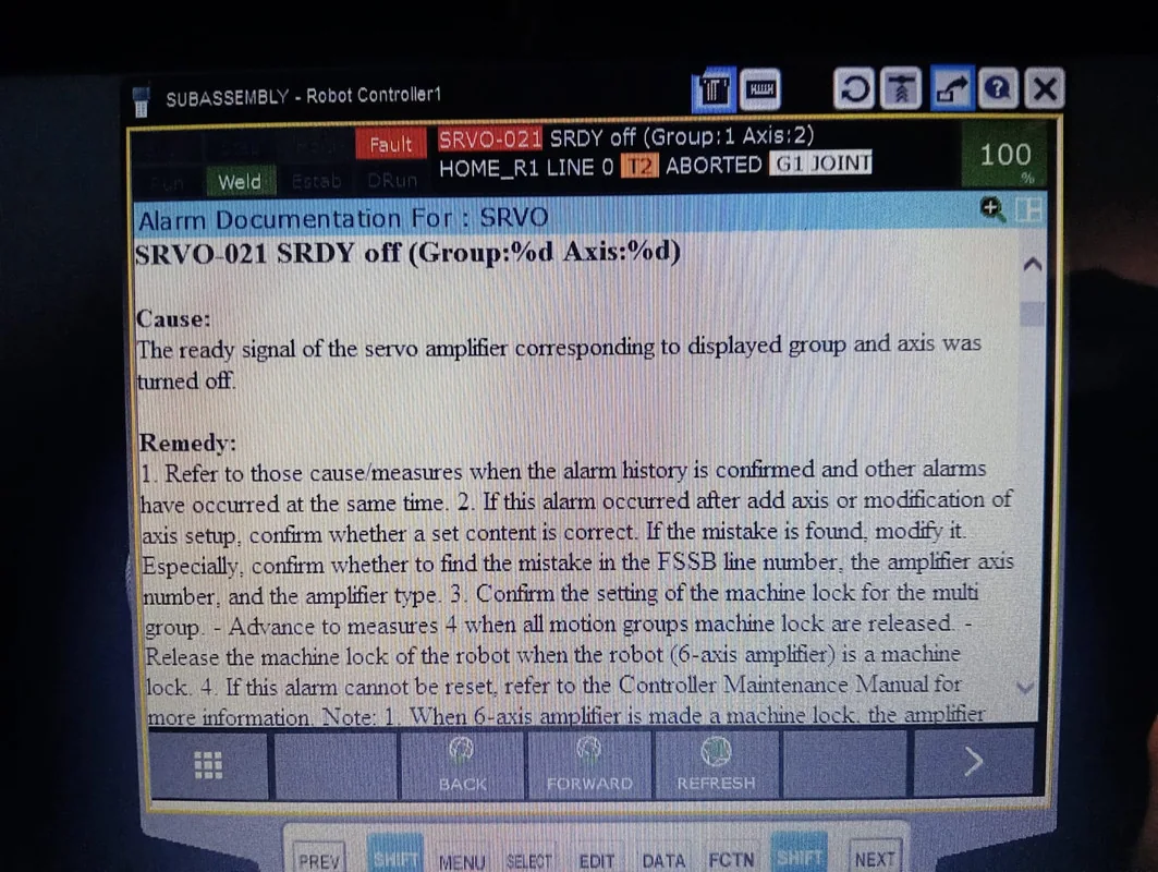
When a FANUC R-30iB robot displays the SRVO-021 SRDY OFF alarm, it indicates that the servo system for the corresponding motion group or axis has not entered the ready state. The fault may originate from the servo amplifier, power supply module, motor power cable, encoder feedback, safety circuit, or mechanical load. This article introduces the troubleshooting sequence for the SRDY OFF alarm, servo link inspection, and power-on verification methods.
In this article
FANUC R-30iB Robot SRVO-021 SRDY OFF Alarm Troubleshooting: Servo Amplifier and Motor Circuit Inspection
When the FANUC R-30iB controller starts the servo system, it needs to confirm that the power supply, servo amplifier, safety circuit, motor, and encoder feedback are all in a permissible state. If the servo amplifier does not return a normal ready signal, the controller may display the SRVO-021 SRDY OFF alarm.
This alarm indicates that the servo system has not entered a ready state, but the servo amplifier cannot be judged as faulty based on the alarm name alone. Abnormal power supply, power cable short circuit, encoder alarm, emergency stop link abnormality, and motor mechanical jamming can all prevent the servo ready signal from being established.
On-site Judgment Conclusion:
If all axes simultaneously show SRDY OFF, first check the common power supply, safety circuit, and servo amplifier status. If the alarm is concentrated on a single axis or an external axis, focus on checking that axis's motor, power cable, encoder feedback, and mechanical load.
Applicability:
This article primarily applies to FANUC industrial robots configured with the R-30iB controller. Differences exist between different robot bodies, software versions, and servo amplifier configurations. The specific alarm meaning, indicator light status, and measurement requirements should be based on the corresponding equipment maintenance manual.
1. What does the SRVO-021 SRDY OFF alarm indicate?
SRDY is an abbreviation for Servo Ready, indicating the servo system's ready state. When SRDY OFF appears, it means the controller has not received a normal servo ready signal, or the ready signal has disappeared during operation.
The robot may exhibit:
- Servo cannot start.
- Alarm immediately after pressing the enable button on the teach pendant.
- All robot axes cannot move.
- A specific motion group or external axis cannot be enabled.
- The robot suddenly stops during operation.
- Temporarily recovers after the control cabinet is restarted.
- SRVO-021 appears simultaneously with other servo alarms.
SRVO-021 is sometimes a subsequent alarm triggered by other faults. Therefore, also check the alarm history for earlier power, overcurrent, encoder, or safety alarms.
2. What information needs to be recorded before repair?
Before starting the inspection, record:
- Complete model of the FANUC robot.
- Specific version of the R-30iB controller.
- Alarm code and complete alarm text.
- Motion group and axis number corresponding to the alarm.
- Whether the alarm occurred during power-up, enable, or operation phase.
- Servo amplifier digital display or indicator light status.
- Whether other alarms appear simultaneously.
- Control cabinet fan and temperature status.
- Whether power outages, collisions, or motor replacements have occurred recently.
- Whether system backups and zero point data are complete.
When viewing the alarm history, focus on analyzing alarms that appeared before SRVO-021. The earliest appearing abnormality is usually closer to the fault source.
3. How to diagnose when all axes alarm simultaneously?
If all robot axes cannot be enabled simultaneously, first check the common conditions:
- Whether the control cabinet input power is normal.
- Whether the main power and control power are stable.
- Whether the emergency stop button is fully reset.
- Whether the safety door and external safety signals meet the conditions.
- Whether the servo amplifier has completed normal startup.
- Whether the DC bus can be established.
- Whether the amplifier fan and cooling system are normal.
- Whether communication between the controller and servo amplifier is normal.
When multiple axes fail simultaneously, the possibility of a common power supply or safety link abnormality is usually higher than multiple servo motors failing at the same time.
4. How to diagnose a single axis or external axis alarm?
If the alarm clearly corresponds to one axis or one external motion group, check the complete servo link for that channel:
- Servo amplifier output channel.
- Motor power cable.
- Motor connector.
- Servo motor winding.
- Motor brake.
- Encoder feedback cable.
- External axis mechanical load.
- Configuration and parameters for the corresponding axis.
For external axes, also check the model matching between the motor and servo amplifier, brake circuit, limit status, and mechanical transmission parts.
5. First check for the presence of other alarms.
SRVO-021 may appear simultaneously with the following types of alarms:
- Servo amplifier overcurrent.
- DC bus voltage abnormality.
- Encoder communication abnormality.
- Motor overheating.
- Regenerative circuit abnormality.
- Fan or module temperature abnormality.
- Emergency stop and safety link abnormality.
- External axis configuration abnormality.
If multiple alarms exist, handle them according to the time of occurrence and causal relationship. Do not only reset SRVO-021 while ignoring earlier overcurrent or encoder faults.
6. Control cabinet power supply inspection.
Power supply abnormalities can prevent the servo amplifier from entering a ready state.
Key inspection points include:
- Control cabinet input voltage.
- Circuit breakers and related protective devices.
- Control power output.
- Servo amplifier power input.
- DC bus related connections.
- Whether terminals are loose, overheated, or burnt.
- Whether the control cabinet grounding is reliable.
After a protective device trips, power should not be restored repeatedly and directly. First check for the presence of short circuits, module damage, or motor line abnormalities.
The control cabinet contains high-voltage energy storage components. After disconnecting the power, wait for the discharge time specified in the equipment manual and confirm there is no dangerous voltage before proceeding with inspection.
7. Key points for servo amplifier inspection.
When a servo amplifier fails, the following may occur:
- Cannot complete self-test after power-up.
- Abnormal amplifier status display.
- Alarm at the moment of enable.
- Module temperature rises rapidly.
- Burnt smell appears inside the control cabinet.
- Ready signal disappears after running for a period.
- Briefly recovers after restart.
Inspection content includes:
- Amplifier model and hardware version.
- Digital display or indicator light status.
- Power module appearance.
- Power supply and output connectors.
- Cooling fan and air ducts.
- Whether the module has accumulated dust, moisture, or oil contamination.
- Whether the interfaces and terminals are discolored or burnt.
After confirming an internal fault, it is usually necessary to inspect the power devices, drive circuit, current sampling, internal power supply, and protection circuit.
8. Motor Power Cable Fault Troubleshooting
Short circuits, grounding, or poor contact in the power cable may prevent the servo amplifier from entering the ready state.
Key inspection points:
- Whether the cable jacket is damaged or crushed.
- Whether the cable is being pulled by robot movement.
- Whether the motor-side connector has liquid ingress or is burnt.
- Whether the control cabinet-side terminals are loose.
- Whether there is abnormal phase-to-phase condition inside the cable.
- Whether the cable shielding and grounding are correct.
- Whether the fault is related to a specific robot posture.
If an alarm occurs when the robot moves to a fixed position, focus on inspecting the robot's moving cables. An undamaged jacket does not necessarily mean the internal conductors and insulation are normal.
9. Servo Motor and Brake Inspection
Abnormal motor windings, internal bearing seizure, or the brake not fully releasing can all cause servo amplifier protection.
Common manifestations include:
- A humming sound when the motor is powered on.
- Difficulty starting the axis or inability to move.
- Rapid temperature rise of the motor.
- Significantly increased resistance to movement in one direction.
- Overcurrent alarm occurring at the moment of enabling.
- Abnormal sounds from the motor or reducer.
During inspection, judgment should be made in conjunction with the power cable, motor windings, insulation, brake, and mechanical load. The measurement range and methods should be based on the corresponding motor technical documentation.
10. Impact of Encoder Feedback Anomalies
The servo system requires reliable encoder position feedback. If the controller cannot confirm the motor position, it may also prohibit servo enabling.
Key inspection points include:
- Whether there is a simultaneous encoder alarm.
- Status of the encoder backup battery.
- Whether the feedback cable is damaged.
- Motor-side and control cabinet-side connectors.
- Whether the connector pins are oxidized or retracted.
- Whether the feedback line has intermittent contact in specific postures.
- Whether the encoder absolute position is valid.
If SRVO-021 and an encoder alarm occur simultaneously, address the feedback link issue first, then confirm the servo ready state.
11. Why Mechanical Seizure Triggers an Alarm
When the robot reducer, bearings, or external mechanism seizes, the motor needs to output excessive torque, which may cause amplifier overcurrent or the ready signal to disappear.
Mechanical inspection includes:
- Whether the robot has experienced a collision.
- Whether the tool or workpiece interferes with the fixture.
- Whether the reducer has abnormal noise or oil leakage.
- Whether there is bearing seizure.
- Whether the motor brake is released.
- Whether external cables restrict robot movement.
- Whether the tool load and center of gravity are correct.
If the alarm occurs during the movement phase after servo enabling, mechanical load should be included in the inspection scope.
12. Judging Faults Based on Alarm Occurrence Stage
【SRDY OFF appears immediately after control cabinet power-on】
Priority checks: Control power supply, servo amplifier, communication, and common power supply.
【Alarm occurs immediately after pressing enable】
Priority checks: Safety status, amplifier output, motor, power cable, and brake.
【Alarm occurs only when a specific axis moves】
Priority checks: Corresponding axis motor, cable, mechanical load, and amplifier channel.
【Alarm occurs after running for a period of time】
Priority checks: Module temperature, fan, control cabinet cooling, motor temperature rise, and mechanical resistance.
【Alarm repeatedly occurs in a specific posture】
Priority checks: Robot body cables, connectors, and mechanical interference.
【Multiple motion groups alarm simultaneously】
Priority checks: Common power supply, safety link, servo amplifier, and control system.
13. SRVO-021 Fault Repair Process
Step 1: Save complete alarm records and occurrence times.
Step 2: Confirm the motion group and axis number corresponding to the alarm.
Step 3: Check if there are earlier associated alarms.
Step 4: Check emergency stop, safety door, and external safety signals.
Step 5: Check control cabinet input and control power supply.
Step 6: Check servo amplifier status and cooling.
Step 7: Check motor power line, feedback line, and connectors.
Step 8: Check motor, brake, and mechanical load.
Step 9: Repair or replace confirmed damaged components.
Step 10: Complete safety function verification, low-speed single-axis verification, and load verification.
14. What to Verify Before Replacing a Servo Amplifier
Before replacement, confirm:
- Complete amplifier model.
- Order number and hardware version.
- Controller model.
- Robot and external axis configuration.
- Axis group controlled by the amplifier.
- Interface and terminal definitions.
- Original module installation location.
- System software and parameter compatibility.
Before disassembly, photograph the module nameplate, wiring, and installation status, and label the connectors. Modules with similar appearance may not be directly interchangeable.
15. Post-Repair Restart Verification
After completing repairs, check in sequence:
- Whether modules, terminals, and connectors are securely installed.
- Whether tools or foreign objects remain inside the control cabinet.
- Whether the fan, air ducts, and cabinet door have returned to normal.
- Whether the controller still has related alarms.
- Whether the emergency stop and safety door functions are normal.
- Whether the servo system can stably enable.
- Whether each axis runs smoothly at low speed in both directions.
- Whether the motor and amplifier have abnormal heating.
- Whether the unloaded program trajectory is normal.
- Whether actual tool operation under load is stable.
- Whether the position and quality of process samples are qualified.
After repair, conduct a continuous operation test to confirm that SRVO-021 and associated alarms do not reappear.
16. Common Questions
Does SRVO-021 always mean the servo amplifier is damaged?
Not necessarily. Power supply, safety circuits, motor, cables, encoder, and mechanical seizure can all cause the servo to be unready.
What should be checked first if all axes alarm simultaneously?
Priority should be given to checking the public power supply, safety chain, servo amplifier status, and controller communication.
After restarting the control cabinet, it returned to normal. Does it still need repair?
It is necessary to continue checking the alarm history, power supply, connectors, fans, and temperature rise. A restart can only temporarily clear some statuses and does not prove that the fault has disappeared.
Can production resume directly after replacing the amplifier?
It is still necessary to verify the configuration and complete safety function verification, low-speed single-axis testing, no-load trajectory testing, load testing, and process validation.
17. Summary
When a FANUC R-30iB robot exhibits an SRVO-021 SRDY OFF alarm, the alarm history should first be reviewed to confirm if there were earlier power, overcurrent, encoder, or safety alarms.
If all axes are abnormal simultaneously, focus should be on checking the public power supply, safety chain, and servo amplifiers; for a single-axis fault, check the corresponding motor, power cable, encoder feedback, and mechanical load.
Technical content reference: FANUC R-30iB Servo Control System Technical Documentation and Industrial Robot Field Repair Experience
Content update time: September 2026
Repair Consultation
If you need to handle FANUC R-30iB robot SRVO-021 SRDY OFF, servo amplifier, or motor faults, please provide the robot model, controller model, complete alarm screen, motion group, faulty axis number, and photos of the amplifier status.
Industrial Robot Repair Hotline: +86 18122009539
Contact Repair Engineer: +86 18122009539
Need a part or repair assessment?
Share the robot model, part number, fault details and destination country with our team.
Contact our team ↗