
ABB MU300 Servo Motor 3HAC040657-001/002 Fault Troubleshooting: Brake, Encoder, and Overheating Inspection
When faults occur in the ABB MU300 servo motors 3HAC040657-001 and 3HAC040657-002, they may cause robot axes to fail to operate, brakes to not release, motor overheating, abnormal vibration, or position feedback alarms. This article introduces troubleshooting methods for motor windings, insulation, brakes, encoders, bearings, and power cables, as well as the zero-point and recommissioning verification process after motor replacement.
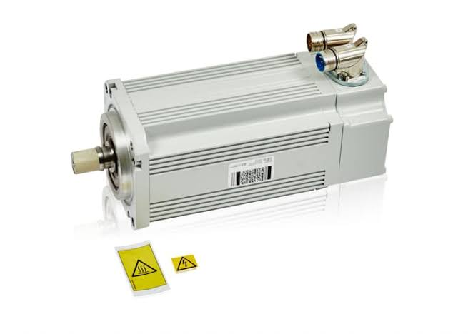
The ABB MU300 servo motor is responsible for the power output and position feedback of the robot joints. When abnormalities occur in the motor windings, brake, encoder, bearings, or connecting cables, the robot may experience issues such as servo failure to start, single-axis immobility, operational jitter, position deviation, and temperature alarms.
On-site diagnostic conclusion: When a robot displays motor-related alarms, one should not immediately conclude that the MU300 motor is damaged. Reducer jamming, excessive mechanical load, short circuits in power cables, poor contact in encoder wiring, and drive unit abnormalities can also produce similar faults. During repair, first identify the faulty axis, then inspect in the order of mechanical components, cables, brake, feedback system, and the motor itself.
1. Confirm the complete motor model
Check the part number, serial number, rated parameters, and encoder configuration on the motor nameplate to confirm whether it is 3HAC040657-001 or 3HAC040657-002. Different suffix numbers may indicate differences in mechanical interface, brake, feedback components, or configuration version. When replacing, do not judge interchangeability based solely on the "MU300" name.
2. Common fault manifestations
MU300 servo motor faults may manifest as the corresponding axis failing to enable, abnormal noise during startup, jitter during operation, impact during direction changes, rapid motor temperature rise, brake failure to release, or unstable position feedback. Some motors may operate in a cold state but generate alarms only after the temperature rises, usually requiring judgment based on operating time and temperature changes.
3. Record alarms and faulty axis
Before repair, save complete alarm information, the faulty axis number, robot posture, and program operating status. Confirm whether the fault occurs during servo enable, acceleration, direction change, braking, or high-speed operation. If alarms are consistently concentrated on the same axis, focus inspection on that axis's motor, reducer, power cable, feedback cable, and drive channel.
4. Distinguish between motor fault and mechanical jamming
When increased operating resistance is caused by reducer, bearing, or external mechanical interference, the controller may also display overcurrent, overload, and position deviation. Check the mechanical motion resistance of the corresponding axis under specified conditions and observe if the fault changes after removing the external load. If motor operation recovers after disconnecting from the mechanical load, continue inspecting the reducer and mechanical structure.
5. Inspect power cables and connectors
Check if the motor power plug and control cabinet side connector are securely locked, and if terminals show signs of burning, pin retraction, oxidation, liquid ingress, or insulation damage. Cables undergo repeated bending during robot movement, and internal wires may break only in specific postures. Therefore, also record whether the fault is related to the robot's position.
6. Check if the brake releases normally
Vertical axes typically rely on the motor brake to maintain position when the servo is off. After abnormalities in the brake coil, power supply line, or mechanical friction plates, issues may arise such as axis immobility, high startup current, operational heating, or robot sinking after stopping. During inspection, confirm the brake power supply, coil status, release sound, and holding capability. Do not force movement of an unreleased brake by increasing drive parameters.
7. Measure motor winding resistance
After disconnecting the motor from the drive, measure the resistance of each phase winding according to the motor documentation and compare them. The three-phase resistances should remain reasonably balanced. If one phase is significantly higher, lower, or completely open-circuit, there may be winding burnout, poor contact at connection terminals, or internal wire breakage. Measurement results should also account for ambient temperature and instrument accuracy.
8. Check winding insulation status
Measure the winding-to-ground insulation according to the corresponding motor's testing requirements to determine if there is moisture ingress, insulation aging, coolant entry, or winding breakdown. Before insulation testing, disconnect the encoder, drive, and other sensitive electronic components. The test voltage and method should comply with the motor documentation requirements to avoid damaging feedback components.
9. Check encoder and feedback lines
Encoder abnormalities may cause robot position jumps, unreasonable current axis angles, servo failure to start, or sudden alarms during operation. Inspect the encoder connector, feedback cable, pins, and shield grounding to confirm there is no liquid ingress, looseness, or internal wire breakage. If the fault changes with cable posture, prioritize handling the feedback harness.
10. Check motor bearings
After motor bearing wear, continuous humming, periodic friction sounds, rough rotation, and motor temperature rise may occur. During inspection, observe if there is abnormal radial or axial play in the motor shaft and distinguish whether the sound originates from the motor bearings or the robot reducer. When replacing only bearings, also ensure assembly, lubrication, and encoder position are not affected.
11. Analyze motor overheating causes
Motor overheating is not necessarily a winding fault; it may also be caused by excessive mechanical load, incomplete brake release, reducer jamming, incorrect load parameters, excessively high motion acceleration, or poor cooling conditions. Compare the temperature of this axis with other axes under the same load or with robots of the same model, and record the relationship between temperature rise and operating time.
12. Check drive output
After confirming no obvious abnormalities in the motor, cables, and mechanical parts, check the output and alarm status of the corresponding drive channel. Abnormalities in the drive module's internal power devices, detection circuits, or connection terminals can also cause single-axis overcurrent, phase loss, and inability to enable. Before performing substitution tests, confirm that the drive module, motor, and software configuration are compatible.
13. Motor repair and replacement requirements
Repair work may include winding treatment, brake repair, bearing replacement, encoder inspection, and connector repair. After repair completion, perform tests for winding balance, insulation, brake, and feedback function. When directly replacing the motor, verify the complete part number, mounting flange, shaft end structure, encoder, and brake configuration.
14. Zero-point handling after installation
Disassembling the motor may alter the positional relationship between the motor shaft and the robot's mechanical joint. After reinstallation, check the revolution counter, mechanical markings, and calibration data according to the robot model and repair scope. If the original positional relationship has changed, it is necessary to re-perform the zero-point calibration for the corresponding axis; do not compensate by modifying program points.
15. Recommissioning operation verification
First, test the repaired axis in manual low-speed mode for forward, reverse, start, and stop, observing sound, vibration, braking, and temperature rise. Then, check a fixed TCP reference point and run a complete program at low speed with no load. After confirming normal trajectory, gradually increase speed. Finally, perform load-bearing production testing and re-check the motor temperature.
16. Summary
When faults occur in the ABB MU300 servo motors 3HAC040657-001/002, first confirm the faulty axis and complete alarm information, then inspect mechanical load, power cables, brake, winding insulation, encoder, bearings, and drive unit. After completing motor repair or replacement, it is also necessary to handle the robot's zero-point and verify TCP, program trajectory, and load-bearing operation status.
Repair Consultation
If you need to address ABB MU300 servo motor 3HAC040657-001/002 overheating, brake abnormalities, encoder faults, or robot single-axis failure to operate, please provide the robot body model, motor nameplate, faulty axis number, complete alarm screen, and operation video.
Industrial Robot Repair Hotline: +86 18122009539
Contact Repair Engineer: +86 18122009539