
KUKA Robot Repair: Intermittent Single-Axis Faults
Diagnose intermittent single-axis faults on KUKA robots by separating cable, connector, motor, drive, feedback, and mechanical causes.
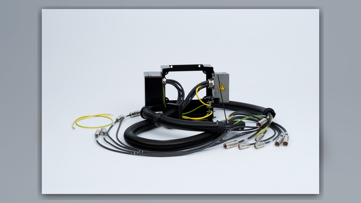
Intermittent single-axis faults require KUKA robot repair based on recorded evidence rather than immediate parts replacement. Potentially involved systems include the axis motor, feedback-related components, brake, moving cable assembly, connectors, controller drive hardware, and mechanical transmission. Before resetting the robot, record the complete alarm, affected axis, robot posture, commanded motion, load condition, and event history. A fault that appears on one axis does not independently prove that its servo motor or drive is damaged.
Symptoms and Scope
This diagnostic approach applies to KUKA industrial robots, including systems using a KR C4 controller, when one axis stops, faults intermittently, or operates only in certain positions. Exact alarm definitions, connector locations, and test procedures depend on the installed robot, controller generation, drive configuration, software version, and documentation.
The scope does not include a confirmed motor, drive, cable, or reducer failure. It also does not cover a robot-wide motor-enable problem affecting every axis. If several axes stop simultaneously, investigate common power, safety, controller, and communication conditions before concentrating on one motor circuit.
Information to Record First
Preserve the alarm history before repeated resets overwrite useful evidence. Record whether the problem occurred during acceleration, steady motion, deceleration, braking, or while the robot was stationary.
Complete alarm code and full text:
Date and exact time:
Faulted axis:
Robot position/posture:
Program step or motion:
Actual speed and load condition:
Reset result:
Time until recurrence:
Related power, communication or feedback alarms:
Also record the robot model, controller model, motor identification, installed options, recent maintenance, collision history, and any work performed on cables or connectors. If the fault follows a particular posture, note the positions of adjacent axes because their movement may bend or twist a shared cable route.
Safety and Preparation
Follow the applicable KUKA operating information and the facility's lockout, energy-control, and safeguarding procedures. Stored energy, gravity-loaded axes, and unexpected brake release can create serious hazards. Internal controller inspection, connector disconnection, and motor removal should be performed only by qualified personnel after the relevant energy sources have been controlled.
Do not repeatedly run a motion merely to reproduce the fault. Observation under motion may be performed only by suitably competent personnel under controlled conditions and according to the manufacturer information and site safety procedure. Stop testing if noise, overheating, unstable movement, cable damage, or an increasing fault frequency indicates greater equipment risk.
KUKA Robot Repair Diagnostic Sequence
- Confirm the exact event. Use the complete alarm text and chronological event history, not a shortened operator description. Determine whether an earlier alarm identifies power, feedback, communication, safety, or drive conditions. The first relevant event may direct the investigation more accurately than the final stop message.
- Verify equipment identity. Record the robot and controller models, affected axis, motor label, drive identification, hardware revision, and connector arrangement. This information is necessary because components that look similar may not be interchangeable. If identification is incomplete, obtain label photographs before selecting a spare or arranging bench inspection.
- Inspect external conditions. With the equipment in an electrically safe state, examine accessible axis cables, dress packs, connector housings, strain-relief points, and cabinet connections for looseness, contamination, impact, abrasion, sharp bending, discoloration, or fluid exposure. Visible damage supports further inspection but does not establish which internal conductor or component has failed.
- Compare the fault with posture and motion. A fault consistently associated with a narrow posture range can indicate a moving cable or connector issue, but it may also reflect mechanical load or routing interference. A fault associated with acceleration or payload does not by itself prove motor winding damage. Confirm the approved payload data and look for tooling changes, collisions, binding equipment, or external forces.
- Separate stationary and motion-related behavior. A fault appearing while the axis is stationary can direct attention toward connections, feedback stability, brake behavior, or controller conditions. A fault appearing only during motion may require evaluation of cable movement, feedback signals, motor loading, drive operation, and mechanical resistance. The event history and controlled observations determine which branch is justified.
- Evaluate the mechanical system. Check for abnormal resistance, unusual noise, impact evidence, leakage, loose mounting, or interference with tooling and peripheral equipment. Mechanical binding can increase servo demand and produce symptoms that resemble electrical trouble. Mechanical inspection must follow the applicable procedure; do not manually force an axis or release a brake without controlling gravity and stored energy.
- Escalate the relevant component. If evidence remains concentrated around the motor circuit, qualified inspection may include the motor, brake, feedback-related component, connectors, and associated cable. If controller evidence points to the drive channel, professional drive testing may be appropriate. Any electrical testing must use the manufacturer procedure and suitable equipment rather than improvised energized measurements.
How to Distinguish Similar Causes
A posture-dependent pattern increases suspicion of a flexing cable or connection, especially when the same axis recovers after its position changes. However, posture also changes joint loading, so this pattern is not conclusive.
Heat discoloration, damaged seals, loose connector retention, or contamination justifies connector and cable inspection. It does not prove that the motor is internally defective. Likewise, unusual motor noise can originate from a brake, bearing, reducer, coupling, or external mechanical load.
An alarm that follows a swapped component may provide useful evidence only when the exchange is permitted by the applicable procedure and both components are confirmed compatible. Do not interchange motors, drives, or feedback-related components solely because their housings appear similar. Configuration and calibration consequences must be assessed before any substitution.
When Repair or Replacement May Be Considered
KUKA servo motor repair may be considered when documented inspection identifies a motor-related defect and the exact unit can be evaluated by a competent repair facility. Drive, cable, connector, or mechanical repair may be more appropriate when evidence points elsewhere. Replacement decisions must match the exact model, part number, hardware revision, connector layout, and system compatibility. Calibration or mastering requirements must also be reviewed before returning the axis to production.
ZHB is an independent industrial robot inspection, repair, and maintenance service provider that also supplies parts to overseas customers. General service information is available at https://autonews.best/services. For a repair inquiry, provide the KUKA robot model, controller model, complete alarm code, alarm history, affected component label, fault conditions, and clear photographs of the robot, motor, connectors, and relevant cabinet hardware.
Verification After Repair or Replacement
Before restart, confirm that connectors are secured, cable routing and strain relief are restored, protective covers are installed, tools are removed, and the work area is clear. Review whether motor replacement or mechanical work requires mastering, calibration, or additional checks under the applicable KUKA procedure.
Qualified personnel should begin with controlled operation at an appropriate reduced operating condition established by the manufacturer information and site procedure. Verify alarm status, axis response, brake behavior, cable movement, unusual noise, and repeatability before restoring automatic production. Test the relevant program path and load condition without deliberately recreating a hazardous fault. Retain the pre-repair and post-repair event records for comparison.
Common Diagnostic Mistakes
Common errors include replacing the motor because one axis is named in an alarm, clearing the event history before recording it, overlooking a posture-dependent cable pattern, ignoring recent tooling changes, and ordering a visually similar component without checking its complete label. Another mistake is treating a successful reset as proof of repair. An intermittent fault remains unresolved until the suspected cause is supported by evidence and the system passes controlled verification.
Conclusion
Effective KUKA robot repair for an intermittent single-axis fault depends on separating motor, feedback, cable, connector, drive, brake, and mechanical possibilities. Preserve the complete alarm history, identify the exact equipment, correlate the event with posture and operating conditions, and inspect low-risk external conditions first. Consider component repair or replacement only after the evidence supports that decision.