
KUKA Robot Repair for Single-Axis Noise Diagnosis
Diagnose single-axis noise on KUKA robots by separating motor, brake, cable, gearbox, lubrication, tooling, and load-related causes before replacement.
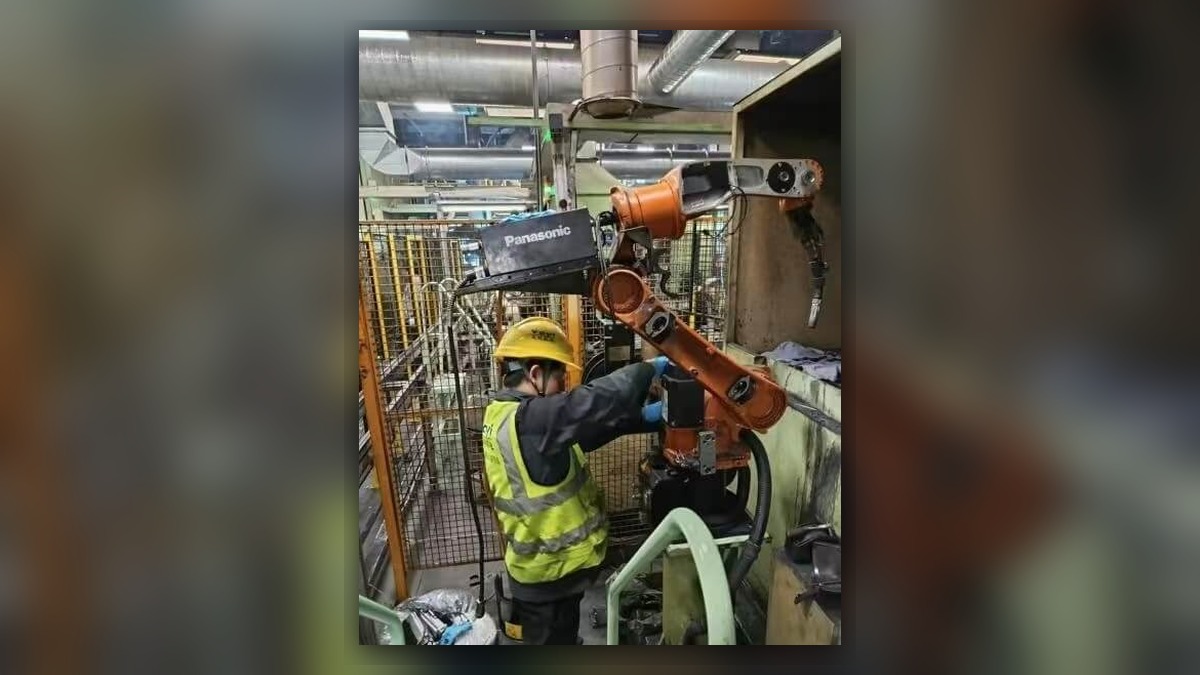
Single-axis noise during KUKA robot operation may involve the servo motor, brake, gearbox, bearings, dress cables, tooling, lubrication condition, or an incorrectly defined load. Before beginning KUKA robot repair, record the complete alarm history, affected axis, robot posture, commanded motion, speed, payload, and recent service work. Noise alone does not prove that the motor or gearbox is damaged. Its location, relationship to motion direction, and repeatability must be established before removing parts or returning the robot to production.
Symptoms and Scope
This diagnostic approach applies generally to KUKA articulated robots when one axis develops clicking, grinding, scraping, humming, or another unusual mechanical sound during movement. Exact inspection procedures depend on the robot model, controller generation, axis design, installed options, and maintenance documentation.
The article does not provide model-specific lubrication quantities, brake tests, connector pinouts, or internal adjustment procedures. It also does not cover a robot that has become structurally unstable or cannot be moved safely. Such conditions require isolation and assessment by qualified personnel.
Information to Record First
Preserve evidence before resetting alarms, changing programs, removing tooling, or disconnecting components. Compare the current condition with maintenance records and any recent collision, motor replacement, cable work, lubrication service, payload change, or tooling modification.
Complete alarm code and full text:
Date and exact time:
Faulted axis:
Robot position/posture:
Program step or motion:
Actual speed and load condition:
Reset result:
Time until recurrence:
Related power, communication or feedback alarms:
Also record whether the noise occurs during acceleration, steady movement, deceleration, stopping, or brake release. Note whether it appears in both directions, within a limited joint-angle range, or only with a particular tool or workpiece. These distinctions help separate axis-internal problems from external interference and load-related conditions.
Safety and Preparation
Stop automatic production and follow the site lockout, energy-isolation, and safeguarding procedure before touching the robot, tooling, cables, or axis components. Account for suspended loads, gravity-affected axes, stored energy, and tooling that could move unexpectedly. Do not loosen a motor, brake, gearbox, or structural fastener without the applicable KUKA service information and suitable support for the mechanism.
Observation under motion may be performed only by suitably competent personnel under controlled conditions, using the applicable manufacturer operating information and site safety procedure. Do not repeatedly run a noisy axis merely to reproduce the symptom, because continued movement could increase damage or create a safety risk.
KUKA Robot Repair Diagnostic Sequence
1. Confirm the affected axis and operating condition. Use the recorded posture, program step, direction, speed, and payload to determine whether the noise consistently follows one joint. If it changes with tooling operation or nearby equipment, inspect those external systems before assuming an internal axis fault.
- Inspect for external contact and loose equipment. With energy safely isolated, examine dress packages, hoses, cable carriers, covers, brackets, tool fasteners, and nearby guarding. Look for rubbing marks, displaced brackets, impact evidence, loose items, and cables that become tensioned in a particular posture. If contact explains the sound, correct the underlying routing or mounting issue according to the approved configuration before further evaluation.
- Review alarms and recent work. A related drive, brake, feedback, temperature, or overcurrent alarm can change the diagnostic direction, but its complete text and context are required. Recent motor, gearbox, mastering, tooling, or cable work may indicate an installation or configuration issue that needs verification. Do not change mastering data or servo parameters simply because noise appeared after service.
- Verify payload and tooling information. Compare the installed tool and carried workpiece with the active load configuration. Incorrect mass, center-of-gravity, or inertia data may affect motion behavior, but the data must be checked against documented tooling information rather than estimated. Correcting load data is not a substitute for inspecting physical damage.
- Assess the sound pattern. Noise near a limited joint position may point to cable contact, localized mechanical wear, or an external obstruction. Noise associated mainly with direction reversal may require examination of mechanical play, mounting security, the brake, or transmission components. A sound associated with motor energization but not joint movement requires a different evaluation from grinding that occurs only under load. These patterns narrow the inspection; they do not confirm a failed component.
- Decide whether component testing is required. If external causes, load configuration, and visible installation issues do not explain the symptom, isolate the suspected motor, brake, or mechanical transmission for professional inspection. KUKA servo motor repair may be considered when evidence supports a motor-related problem, such as abnormal bearing condition, connector damage, contamination, or a relevant electrical test result obtained using approved procedures. Gearbox or joint repair should be considered separately when the evidence is mechanical.
When Repair or Replacement May Be Considered
Do not replace the servo motor solely because the noise appears to come from its mounting area. Sound can travel through the robot casting, making a gearbox, brake, cable, or tool-related fault appear motor-related. Removed components should be identified and tested before a repair decision whenever practical.
Any replacement must match the exact KUKA robot model, component part number, hardware revision, connector layout, brake arrangement, and installation requirements. Compatibility should be verified from the installed component label and applicable technical documentation, not visual similarity alone.
ZHB is an independent industrial robot inspection, repair, and maintenance service provider that also supplies parts to overseas customers. Its broader industrial robot repair service is available at https://autonews.best/services. For one repair inquiry, provide the robot model, controller model, complete alarm code, alarm history, component label, fault conditions, and clear photographs of the robot axis, motor label, connectors, and any visible damage.
Verification After Repair or Replacement
Before restart, verify that tools, covers, connectors, cables, fasteners, and protective devices have been restored correctly. Confirm that no foreign material remains in the work area and that the installed payload configuration matches the actual tool and workpiece. If mastering or calibration may have been affected, follow the model-specific KUKA procedure rather than assuming the previous data remains valid.
Qualified personnel should conduct the initial controlled movement in accordance with the manufacturer information and site safety plan. Begin with conditions that limit risk, then confirm axis movement, brake behavior, alarm status, cable clearance, repeatability, and operation through the required production range. Do not force the robot through the original noisy motion when unresolved mechanical resistance, interference, or abnormal sound remains.
Common Diagnostic Mistakes
Common errors include replacing the motor before checking external cable contact, ignoring a recent tooling change, estimating payload data, clearing alarms without saving the history, and assuming that noise location identifies the damaged part. Another mistake is continuing production because the robot still completes its cycle. A developing mechanical or brake-related condition may require prompt isolation even when no alarm is active.
Conclusion
Effective KUKA robot repair for single-axis noise depends on preserving fault evidence and separating external contact, load configuration, cabling, motor, brake, and transmission causes. The sound itself is only a symptom. A safe, model-specific inspection and controlled verification process provides a stronger basis for deciding whether maintenance, professional testing, component repair, or replacement is appropriate.