
ABB IRB 5500 Painting Robot High Voltage Alarm Repair: Atomizer, Grounding, and Safety Interlock Troubleshooting
When an ABB IRB 5500 robot configured for electrostatic painting experiences issues such as failure to start due to high voltage, immediate high voltage disconnection after establishment, frequent alarms during the painting process, or a decrease in paint transfer efficiency, the fault may originate from the high voltage generation unit, atomizer, grounding circuit, air control unit, paint contamination, or safety interlocks. This article introduces the control chain of the high-voltage painting system, fault diagnosis methods, and the verification process for returning the system to operation.
In this article
ABB IRB 5500 Painting Robot High Voltage Alarm Repair: Troubleshooting Atomizer, Grounding, and Safety Interlocks
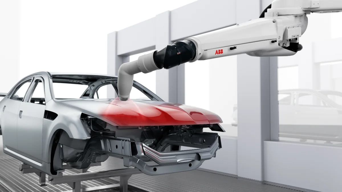
ABB IRB 5500 is a painting robot used in automotive and industrial coating production lines. When configured for electrostatic spraying, the system requires a high-voltage electric field to improve the adhesion efficiency of the coating onto the workpiece surface.
An electrostatic spraying system typically consists of the robot body, control system, atomizer, high-voltage generation unit, air control unit, coating delivery system, grounding circuit, and spray booth safety system. Any abnormality in any of these components can cause the high voltage to fail to establish or to be interrupted during the spraying process.
On-site diagnostic conclusions:
If high voltage cannot be established before startup, first check the safety interlocks, workpiece grounding, high voltage enable, and air conditions. If high voltage is established but immediately cuts off, focus on checking for leakage, contamination, insulation, and atomizer status. If intermittent alarms occur only during the spraying process, then check for coating buildup, hose condition, robot posture, and high-voltage wiring.
Scope of application:
This article primarily applies to ABB IRB 5500 series robots equipped with electrostatic spraying systems. The structure may vary for different atomizers, high-voltage units, and spray control systems. The specific alarm meanings, testing methods, and allowable ranges should be based on the equipment nameplate, electrical diagrams, and corresponding technical manuals.
1. How the Electrostatic Spraying High Voltage System Works
Before normal spraying, the control system needs to sequentially confirm:
- Spray booth safety conditions are normal.
- Emergency stop and safety doors have been reset.
- Exhaust and fire protection interlocks are normal.
- The robot is in a position where spraying is permitted.
- Atomizing air, shaping air, and bearing air meet requirements.
- Workpiece and conveying equipment grounding is normal.
- Coating and cleaning medium switching status is correct.
- The high-voltage generation unit is in a ready state.
- The control system issues the high voltage enable command.
- The actual high voltage feedback is within the allowable range.
If any precondition is not met, the control system may prohibit high voltage startup.
2. Common Manifestations of High Voltage Faults
On-site issues may include:
- No output after high voltage is enabled.
- High voltage drops immediately after being established.
- High voltage frequently disconnects during the spraying process.
- Significant deviation between actual and set high voltage values.
- System displays leakage current or high voltage overload alarms.
- Abnormal discharge appears on the atomizer surface.
- Paint transfer efficiency on the workpiece is noticeably reduced.
- Increased paint overspray and spray booth contamination.
- Alarms begin after changing coating or cleaning.
- High voltage interrupts when the robot moves to a specific posture.
Simultaneously record alarms displayed by the robot controller, spray control system, and high-voltage unit; do not just record "high voltage fault."
3. Information to Record Before Repair
Before starting inspection, record:
- Complete robot model and serial number.
- Robot and spray control system versions.
- Atomizer model.
- High-voltage unit model and complete material number.
- Complete alarm codes and alarm text.
- High voltage set value and actual feedback changes.
- Whether the fault occurs during startup, spraying, or cleaning phase.
- Coating and cleaning media used.
- Whether the fault is related to color changes.
- Whether the fault consistently occurs at a specific robot posture.
- Whether the atomizer, high-voltage cable, or coating lines have been replaced recently.
- Grounding inspection and maintenance records.
It is recommended to photograph the atomizer, high-voltage unit, grounding connections, and alarm screens, and record operations before and after the fault occurs.
4. If High Voltage Cannot Start, First Check Safety Interlocks
The high voltage system is typically controlled by multiple safety conditions.
Key checks include:
- Whether the emergency stop status is normal.
- Whether the spray booth safety doors are closed.
- Whether the exhaust system is operating normally.
- Whether fire protection and combustible gas monitoring permit spraying.
- Whether the robot is located in an area where high voltage activation is permitted.
- Whether atomizer air conditions are met.
- Whether cleaning valve and coating valve statuses are correct.
- Whether the high-voltage unit returns a ready signal.
- Whether the external PLC issues a spray enable signal.
If any interlock is not satisfied, the high-voltage unit may be perfectly functional, but the system will not send the high voltage enable command.
5. Troubleshooting Workpiece Grounding Faults
Electrostatic spraying requires a reliable grounding circuit formed by the workpiece, hangers, conveyor chain, and spray booth equipment.
Grounding abnormalities may arise from:
- Paint buildup on the contact surface between the workpiece and hanger.
- Hangers being covered by coating after prolonged use.
- Contamination or corrosion at conveyor chain connection points.
- Loose, broken, or incorrectly connected grounding wires.
- Improper installation of insulating components on fixtures.
- Workpiece not fully contacting positioning devices.
- Oil, grease, or oxidation layers on grounding point surfaces.
Grounding status should not be judged by visual inspection alone; it should be tested using appropriate instruments according to the spray equipment's technical requirements. Specific allowable values should be based on on-site processes and equipment manuals.
6. Why Atomizer Contamination Can Cause High Voltage Alarms
During the spraying process, the atomizer exterior, insulating components, and high-voltage output area may accumulate coating.
Contamination can create abnormal conductive paths, leading to:
- High voltage leakage.
- Increased leakage current.
- Immediate protection after high voltage is established.
- Discharge marks appearing on the atomizer surface.
- Temporary abnormalities due to residual solvents after cleaning.
- Unstable high voltage feedback.
During inspection, focus on:
- Whether the atomizer exterior has paint buildup.
- Whether insulating areas are covered by coating.
- Whether contamination exists in the high-voltage connection area.
- Whether a large amount of liquid remains after cleaning.
- Whether coating hoses and air lines are damaged.
- Whether the atomizer shows signs of burning or carbonization.
Cleaning methods and materials should comply with the atomizer's technical requirements. Avoid using tools or solvents that may damage insulating materials.
7. Judging Immediate High Voltage Disconnection After Establishment
[Alarm immediately after high voltage is enabled]
Priority checks: High voltage output terminal, atomizer insulation, grounding status, and safety interlocks.
[Normal during air spray, alarms when approaching the workpiece]
Priority checks: workpiece grounding, spraying distance, robot trajectory, and partial discharge.
[Alarm during first spray after cleaning]
Priority checks: residual liquid on atomizer surface, cleaning valve status, and media switching.
[Alarm when moving to a fixed posture]
Priority checks: high-voltage lines, paint hoses, wrist cables, and mechanical pulling.
[Alarm after continuous spraying for a period]
Priority checks: paint buildup on atomizer, high-voltage unit temperature rise, cooling, and air status.
[Alarm after replacing atomizer]
Priority checks: atomizer model, installation, grounding, high-voltage connection, and system configuration.
8. High-voltage generation unit inspection
After confirming that interlocks, grounding, and atomizer status are normal, the high-voltage generation unit should be inspected.
Inspection items include:
- Whether module power supply is stable.
- Whether the high-voltage enable signal is received.
- Whether the high-voltage ready signal is normal.
- Whether the actual high voltage and current feedback are reasonable.
- Whether the module has experienced overtemperature alarms.
- Whether cooling and installation environment are normal.
- Whether connectors are loose or contaminated.
- Whether high-voltage lines and insulation components are damaged.
- Whether there are abnormal odors or discharge traces on the module.
The high-voltage system contains dangerous voltage. Internal inspection, insulation testing, and module repair should be performed by personnel with appropriate experience in accordance with equipment technical requirements.
9. Air control unit inspection
Spray atomizers typically require multiple compressed air lines, including bearing air, atomizing air, and shaping air. Abnormal air conditions may affect atomizer operation and high-voltage permission.
Key inspection points include:
- Whether air supply pressure is stable.
- Whether the air is dry and clean.
- Whether filters are clogged.
- Whether solenoid valves operate normally.
- Whether pressure sensor feedback is accurate.
- Whether air hoses are damaged, bent, or leaking.
- Whether there are communication alarms in the air control unit.
- Whether the air interlocks required by the atomizer are satisfied.
If bearing air is insufficient, some high-speed rotary bell systems will prohibit startup or stop operation to protect the atomizer.
10. Paint conductivity and process media inspection
Different paints, cleaning agents, and ratios may have different conductive properties.
The following situations may affect high-voltage status:
- Changes in paint batch or formulation.
- Incorrect dilution ratio.
- Residual cleaning media.
- Water ingress into paint lines.
- Incomplete color changeover.
- Media with higher conductivity entering high-voltage areas.
- Paint leakage contaminating insulation components.
If a fault occurs after changing paint or color switching, media status, valve group operation, and cleaning procedures should be checked.
11. Robot posture and high-voltage line inspection
If the robot alarms only at fixed postures, inspect the moving lines inside the wrist and arm.
Key points include:
- Whether high-voltage lines are excessively bent.
- Whether paint hoses are stretched or crushed.
- Whether air hoses flatten during wrist movement.
- Whether connectors become loose due to vibration.
- Whether lines rub against the robot housing.
- Whether the atomizer mounting flange is loose.
- Whether the robot wrist has experienced collisions.
Under conditions where spraying media is turned off and site safety requirements are met, the same trajectory can be run at low speed to observe line posture and signal changes.
12. Spray control I/O inspection
Typically, the robot, PLC, and spray system need to exchange:
- Spray enable signal.
- High-voltage ready signal.
- High-voltage enable signal.
- Actual high-voltage status.
- Atomizer operation status.
- Air pressure normal signal.
- Paint valve and cleaning valve status.
- Spray booth safety interlocks.
- Spray system fault signal.
During inspection, simultaneously observe robot I/O, PLC status, and spray controller feedback to confirm which signal link the fault occurs in.
13. High-voltage alarm repair procedure
Step 1: Save alarms from the robot, spray system, and high-voltage unit.
Step 2: Confirm whether the fault occurs during startup, spraying, or cleaning phase.
Step 3: Check emergency stop, spray booth, and exhaust safety interlocks.
Step 4: Check workpiece, hanger, and conveyor system grounding.
Step 5: Check atomizer contamination, insulation, and installation status.
Step 6: Check air control unit and pressure feedback.
Step 7: Check paint, cleaning media, and color changeover status.
Step 8: Check high-voltage lines, hoses, and wrist lines.
Step 9: Check high-voltage generation unit and control I/O.
Step 10: After repairing the fault, complete dry run, test spray, and process verification.
14. Post-repair restart verification
After completing repairs, check in sequence:
- Spray booth safety and exhaust interlocks.
- Workpiece, hanger, and conveyor system grounding.
- Atomizer cleanliness and installation status.
- Air pressure and atomizer operation status.
- High-voltage ready, enable, and feedback signals.
- Robot low-speed dry run trajectory.
- Status of wrist lines in various postures.
- Low-parameter test spray using a test piece.
- Whether actual high-voltage value and current feedback are stable.
- Whether coating coverage, atomization, and transfer efficiency are normal.
- Whether high-voltage alarms reappear after continuous operation.
After repair completion, inspect the test spray workpiece for film thickness, appearance, color difference, sagging, particles, and coverage status.
15. Common issues
Does a high-voltage alarm always mean the high-voltage generator is damaged?
Not necessarily. Workpiece grounding, atomizer contamination, media conductivity, and safety interlocks can all cause high-voltage alarms.
Why does it spray normally in air but alarm when approaching the workpiece?
Check workpiece grounding, spraying distance, trajectory, and whether there is partial discharge on the atomizer.
What causes high-voltage failure to start after cleaning?
It may be related to residual liquid on the atomizer surface, incomplete cleaning media switching, or abnormal status of related valves.
Can high voltage be turned on immediately after cleaning the atomizer?
Operate according to the corresponding equipment cleaning and drying requirements, and confirm that surface and insulation areas are in normal condition before testing.
16. Daily Maintenance Recommendations
- Regularly clean the atomizer and insulation areas.
- Periodically inspect the grounding of workpieces and hangers.
- Check the wrist high-voltage cables and media hoses.
- Inspect air filters and pressure status.
- Establish high-voltage alarm and cleaning records.
- Monitor conductivity and parameter changes after changing coatings.
- After a robot collision, inspect the atomizer, flange, and pipelines.
- Do not forcibly activate high voltage by bypassing safety interlocks.
17. Summary
When an ABB IRB 5500 painting robot exhibits a high-voltage alarm, troubleshooting should follow the sequence: "Safety Interlock—Workpiece Grounding—Atomizer Insulation—Air Conditions—Process Media—High-Voltage Unit."
Failure to start high voltage is typically related to preconditions and enable signals; if high voltage disconnects immediately after being established, focus on checking for leaks, contamination, and grounding; fixed posture alarms require inspection of wrist movement pipelines.
Technical content references: ABB IRB 5500 painting system structure, electrostatic painting equipment technical documentation, and on-site painting robot repair experience.
Content update time: September 2026
Repair Consultation
For repair of ABB IRB 5500 painting robots, atomizers, high-voltage generation units, or air control systems, please provide the robot model, painting system configuration, complete alarm screens, high-voltage feedback, and fault videos.
Industrial robot repair hotline: +86 18122009539
Contact repair engineer: +86 18122009539
Need a part or repair assessment?
Share the robot model, part number, fault details and destination country with our team.
Contact our team ↗