
ABB IRBP R Positioner External Axis Fault Repair: Troubleshooting Enable Failure, Desynchronization, and Zero Point Offset
After an ABB IRBP R positioner is integrated with an IRC5 robot to form a coordinated welding system, faults such as the external axis failing to enable, rotational position deviation, desynchronization between the robot and the positioner, encoder alarms, or zero point loss may occur. This article introduces the troubleshooting methods for the external axis's drive and feedback chain, mechanical unit configuration, brake, encoder, reducer, and coordinated motion.
In this article
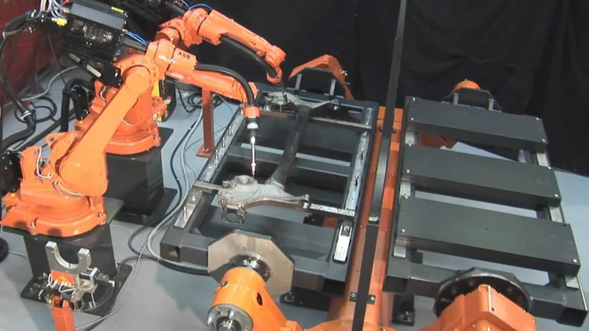
ABB IRBP series positioners are often used with industrial robots to form coordinated welding or workpiece flipping systems. The IRC5 controller manages the positioner as an external mechanical unit, allowing the robot's TCP to maintain the correct position and orientation relative to the workpiece while the positioner rotates.
The external axis system typically includes the positioner mechanical body, servo motor, encoder, brake, reducer, drive module, SMB measurement system, and IRC5 mechanical unit configuration.
On-site diagnostic conclusions:
When an external axis cannot be enabled, first check the safety status, drive module, motor power cables, brake, and feedback link. When the positioner can rotate but is not synchronized with the robot, focus on checking the mechanical unit configuration, workpiece coordinate system, coordinated motion settings, and zero point data.
Scope of Application:
This article primarily applies to ABB IRBP R positioners and IRC5 robot coordinated motion systems. Configurations differ based on load capacity, number of axes, drive module, and RobotWare version. Specific parameters, alarm meanings, and calibration procedures should be based on the equipment nameplate, electrical diagrams, and corresponding technical manuals.
1. How the External Axis System Works
In a coordinated motion system, the IRC5 controller needs to control both the robot axes and the positioner axes simultaneously.
Normal operation requires:
- Normal power supply to the external axis servo motor.
- The drive module can correctly control the motor.
- Normal feedback from the encoder or resolver.
- The brake can release according to commands.
- The IRC5 correctly identifies the positioner mechanical unit.
- Accurate zero point and calibration data for the external axis.
- Correct association between the workpiece coordinate system and the positioner mechanical unit.
- The program selects the correct coordinated motion mode.
Any abnormality in these links can cause external axis alarms or trajectory deviations.
2. Common Fault Manifestations of IRBP R Positioners
On-site issues may include:
- Positioner servo cannot be enabled.
- External axis does not rotate at all.
- Motor rotates but the worktable does not move.
- Positioner vibrates after enabling.
- Overcurrent or following error occurs during rotation.
- Alarm occurs when the external axis reaches a fixed angle.
- Controller indicates encoder or measurement system abnormality.
- External axis zero point lost after power-off.
- Robot and positioner coordinated motion desynchronization.
- Weld seam trajectory shifts when the positioner rotates.
- Rebound or positioning error occurs after the positioner stops.
- Abnormal noise during worktable rotation.
First, distinguish between drive faults, mechanical faults, feedback faults, and coordinate configuration issues.
3. Information to Record Before Repair
Before starting inspection, record:
- Complete ABB robot model.
- Complete IRBP positioner model and serial number.
- IRC5 controller and RobotWare version.
- External axis mechanical unit name.
- Alarm code and complete alarm text.
- External axis number corresponding to the alarm.
- Drive module model and material number.
- Servo motor and encoder information.
- Positioner angle when the fault occurred.
- Workpiece weight and center of gravity.
- Whether coordinated motion is enabled.
- Whether the motor, reducer, or SMB board has been replaced recently.
- Status of system, parameter, and calibration data backups.
It is recommended to photograph the positioner nameplate, motor, connectors, control cabinet modules, mechanical zero point marks, and alarm screens.
4. How to Check When an External Axis Cannot Be Enabled
When an external axis cannot be enabled, first check:
- Whether the IRC5 has correctly loaded the external axis configuration.
- Whether the external mechanical unit is in an active state.
- Whether the emergency stop and safety gates have been reset.
- Whether the drive module is powered on normally.
- Whether the motor power cables are connected correctly.
- Whether the encoder feedback is normal.
- Whether the brake meets the release conditions.
- Whether there are limits or mechanical interference on the external axis.
- Whether there are other associated alarms in the control system.
If the robot body can be enabled but only the positioner cannot, focus on checking the external axis configuration, independent drive channel, and corresponding motor circuit.
5. Drive Module Fault Troubleshooting
External axis drive module abnormalities may manifest as:
- Abnormal indicator status after power-on.
- Immediate alarm when the external axis is enabled.
- Overcurrent during motion.
- Overheating after running for a period.
- Drive module communication interruption.
- Temporary recovery after control cabinet restart.
Inspection items include:
- Module input power supply.
- DC busbar and related connections.
- Drive output terminals.
- Communication status between the module and IRC5.
- Cooling fan and heat dissipation channels.
- Whether the module model matches the external axis configuration.
- Whether there is dust accumulation, moisture, or overheating inside the control cabinet.
An overcurrent alarm does not necessarily indicate a damaged drive module; motor short circuits, brakes not releasing, and reducer jamming can also trigger protection.
6. Servo Motor and Power Cable Inspection
External axis motor faults can cause failure to start, vibration during operation, and abnormal current.
Key inspection points include:
- Whether the motor power cables are damaged or crushed.
- Whether the control cabinet side terminals are loose.
- Whether the motor connector has liquid ingress or burn marks.
- Whether there is an abnormality between motor windings.
- Whether the motor insulation status meets requirements.
- Whether the motor runs with abnormal heating.
- Whether there is abnormal noise from the motor bearings.
- Whether the connection between the motor and reducer is loose.
If an external axis alarms at a specific rotation angle, check whether the flexible cable and cable carrier are being pulled.
7. Judging Brake Failure to Release
The brake is used to hold the worktable and workpiece position when the positioner is stopped. After the servo is enabled, the brake needs to release according to the control logic.
Brake abnormalities may manifest as:
- Motor emits a humming sound but the worktable does not rotate.
- Enable instant overcurrent occurs.
- External axis startup difficulty.
- Worktable low-speed operation is unstable.
- Rapid temperature rise in motor and brake areas.
- Operation resistance in a certain direction significantly increases.
Inspection includes brake power supply, control lines, connectors, and mechanical condition. Do not directly apply external voltage to the brake without understanding the interface definition.
8. Encoder and Feedback Line Faults
Encoders are used to feedback the actual angle of the positioner axis. If the feedback is abnormal, the IRC5 may not establish a correct position closed loop.
Common manifestations include:
- External axis position display jumps.
- Encoder or measurement system alarm.
- External axis cannot be enabled.
- Position data lost after power-off.
- Worktable actual position does not match the teach pendant angle.
- Alarm when the positioner runs to a fixed angle.
Key inspection points include:
- Motor-side feedback connector.
- Control cabinet-side feedback interface.
- Moving feedback cable in the cable carrier.
- Whether connector pins are bent or oxidized.
- Cable shielding and grounding status.
- SMB board, battery, and measurement system communication.
- Whether the fault is related to the positioner angle.
When multiple external axes show position abnormalities simultaneously, first check the common power supply, SMB, and communication lines.
9. How to Determine External Axis Zero Offset
External axis zero point abnormality may cause:
- Teach pendant angle does not match the worktable actual position.
- Workpiece coordinate overall rotation or offset.
- Robot deviates from the weld seam during coordinated motion.
- Existing program shows position error at fixed angles.
- Mechanical marks cannot align after the positioner returns to zero.
- Position abnormality after replacing motor, encoder, or reducer.
During judgment, check:
- Positioner mechanical zero mark.
- External axis angle displayed on the teach pendant.
- Historical calibration data.
- Fixed reference point or calibration fixture.
- Association between workpiece coordinate and mechanical unit.
- Whether the external axis has undergone mechanical displacement.
Do not compensate for external axis zero deviation solely by modifying welding program points.
10. Revolution Counter and SMB Check
If the external axis uses the ABB measurement system, the revolution counter and SMB status affect the absolute position.
Key inspection points include:
- Whether there is a low battery voltage alarm for the SMB.
- Whether the battery plug and wiring are normal.
- Whether the external axis revolution counter is valid.
- Whether the IRC5 can normally recognize the external mechanical unit.
- Whether motor feedback data is stable.
- Whether the battery was replaced in a power-off state recently.
- Whether the encoder or servo motor has been replaced.
Before updating the revolution counter, confirm the external axis actual mechanical position and zero mark to avoid writing an incorrect position.
11. Reducer and Mechanical Transmission Check
Positioner mechanical faults may manifest as:
- Periodic abnormal noise during low-speed operation.
- Impact during forward/reverse direction change.
- Worktable rebound after stopping.
- Increased operation resistance at fixed angles.
- Reducer oil leakage or abnormal temperature rise.
- Motor rotates but worktable does not move.
- Positioning error significantly increases under heavy load.
Inspection includes:
- Reducer gear and bearing condition.
- Motor and reducer coupling.
- Worktable support bearings.
- Mounting bolts and positioning structure.
- Lubrication and sealing status.
- Workpiece weight and eccentric load.
If the center of gravity of the workpiece carried by the worktable deviates from the rotation center, it may significantly increase reducer and motor load.
12. Why Robot and Positioner Are Not Synchronized
Lack of synchronization in coordinated motion may stem from configuration, coordinates, feedback, or mechanical issues.
Common causes include:
- Program does not use correct coordinated motion settings.
- External mechanical unit is not activated.
- Workpiece coordinate is not correctly associated with the positioner.
- External axis zero point has shifted.
- Encoder feedback is unstable.
- Positioner reducer backlash has increased.
- Robot TCP has changed.
- Workpiece clamping position has changed.
- Robot or positioner calibration data is abnormal.
If the robot and positioner operate normally individually, but the trajectory deviates during coordinated welding, prioritize checking mechanical unit association, workpiece coordinates, TCP, and coordinated motion program.
13. Workpiece Coordinate Check
During coordinated welding, the workpiece coordinate should change correctly with the positioner movement.
Check includes:
- Whether the workpiece coordinate is established on the correct positioner mechanical unit.
- Whether the coordinate origin matches the actual fixture.
- Whether the coordinate direction is correct.
- Whether the fixture has moved or been reinstalled.
- Whether workpiece locating pins and clamps are worn.
- Whether the correct coordinate is called for left/right stations.
- Whether the program selects the correct station.
If all weld seams show an overall offset in the same direction, first check the workpiece coordinate and fixture reference.
14. External Axis Load Parameter Check
The positioner load capacity is not only related to workpiece weight but also affected by center of gravity and inertia.
Parameter errors may cause:
- Jitter during acceleration and deceleration.
- External axis following error.
- Drive module overcurrent.
- Increased braking distance.
- Worktable rebound after stopping.
- Reducer and motor temperature rise.
After replacing the workpiece or fixture, re-verify total weight, center of gravity position, and moment of inertia; do not only update the workpiece weight.
15. Determining Direction Based on Fault Conditions
【External axis completely cannot be enabled】
Priority checks: Safety status, mechanical unit configuration, drive module, motor, and feedback link.
【Motor hums but does not rotate after enabling】
Priority checks: Brake, power cable, and mechanical jamming.
【Alarm occurs at fixed angles】
Priority checks: Moving cable, encoder feedback, reducer, and mechanical interference.
【Overcurrent occurs under heavy load】
Priority checks: workpiece weight, center of gravity, reducer resistance, and motor status.
【Robot and Positioner Coordinated Trajectory Deviation】
Priority checks: external axis zero point, workpiece coordinate, TCP, and coordinated motion configuration.
【Position Data Loss After Power Off】
Priority checks: SMB battery, revolution counter, and feedback system.
16. IRBP R External Axis Repair Procedure
Step 1: Save alarm log and current mechanical position.
Step 2: Record robot, positioner, and IRC5 configuration information.
Step 3: Back up system, programs, and calibration data.
Step 4: Check safety circuit and mechanical unit status.
Step 5: Check drive module, power cables, and servo motor.
Step 6: Check brake and mechanical transmission.
Step 7: Check encoder, feedback cables, and SMB system.
Step 8: Confirm external axis mechanical zero point and revolution counter.
Step 9: Check workpiece coordinate, TCP, and coordinated motion configuration.
Step 10: After repair, complete single-axis, coordinated motion, and process verification.
17. Post-Repair Restart Verification
After completing repairs, check in sequence:
- No tools or foreign objects are left inside the positioner.
- Motors, reducers, and connectors are securely installed.
- Emergency stop, safety door, and limit signals are normal.
- External axis calibration and revolution counter status are normal.
- Low-speed forward and reverse operation is smooth.
- Brake release and holding functions are normal.
- Position feedback is stable at different angles.
- No abnormal noise or temperature rise during no-load rotation.
- Low-speed loaded operation is normal after installing the workpiece.
- Robot and positioner coordinated motion trajectory is correct.
- TCP and workpiece coordinate status are normal.
- Welding sample trajectory and quality are acceptable.
When first restoring coordinated programs, reduce speed and focus on observing the distances between the robot, workpiece, fixture, and positioner.
18. Common Issues
Does an external axis failing to enable always mean a damaged drive?
Not necessarily. Mechanical unit configuration, safety circuit, brake, motor, and encoder feedback can all cause failure to enable.
The positioner runs fine alone, so why is there deviation in coordinated welding?
Check the external axis zero point, workpiece coordinate, robot TCP, and coordinated motion settings.
Does replacing an external axis motor require recalibration?
Replacing the motor or encoder may change positional relationships. Confirm the zero point and revolution counter according to the corresponding equipment manual.
Why does it alarm after installing the workpiece when it's fine under no-load?
Check the workpiece weight, center of gravity, inertia, brake, and reducer mechanical condition.
19. Daily Maintenance Recommendations
- Regularly check positioner motor and reducer temperature.
- Check cable carriers and moving cables.
- Check brakes and limit signals.
- Regularly check for reducer oil leaks and operating sounds.
- Save external axis calibration and revolution counter data.
- Update load parameters after changing workpieces or fixtures.
- Regularly verify workpiece coordinates and coordinated trajectories.
- Check mechanical zero point and reducer backlash after a collision.
20. Summary
When an ABB IRBP R positioner experiences failure to enable, position deviation, or unsynchronized coordinated motion, troubleshoot in the order of: "Mechanical Unit Configuration — Safety Status — Drive Module — Motor and Brake — Encoder Feedback — Zero Point and Coordinates."
If an external axis can run alone but coordinated trajectory deviates, focus on checking the zero point, workpiece coordinate, and TCP. If the motor does not rotate after enabling, check the brake and mechanical jamming. If there is an alarm at a fixed angle, check moving cables and feedback lines.
Technical content references: ABB IRBP positioner, IRC5 external axis control system technical documentation, and industrial robot coordinated motion repair experience.
Repair Consultation
For repair of ABB IRBP R positioner, external axis drive, servo motor, or coordinated motion faults, please provide robot model, positioner model, IRC5 version, alarm screen, mechanical unit name, and fault video.
Industrial Robot Repair Hotline: +86 18122009539
Contact Repair Engineer: +86 18122009539
Need a part or repair assessment?
Share the robot model, part number, fault details and destination country with our team.
Contact our team ↗