
ABB Robot DSQC663 Drive Overcurrent Alarm Repair: Troubleshooting Methods from Mechanical Load to Drive Module
When an ABB robot DSQC663 drive triggers an overcurrent alarm, the fault may not originate from the drive module itself; it could also be related to mechanical load, servo motors, power cables, brakes, or cooling conditions. This article focuses on DSQC663 drive overcurrent faults, introducing methods for recording alarm information, determining the fault scope, on-site inspection, professional repair, and restart verification, aiming to help maintenance personnel reduce misjudgments and unnecessary part replacements.
In this article
ABB robots may experience drive overcurrent, servo enable failure, or single-axis stoppage during startup, acceleration, deceleration, or loaded operation. Some on-site personnel may directly conclude that the drive is damaged upon seeing an overcurrent alarm, but the actual situation is often not so.
An overcurrent alarm indicates that the drive system has detected abnormal current. Mechanical jamming, motor failure, power cable short circuit, brake not fully released, and abnormal power components inside the drive module can all trigger similar alarms.
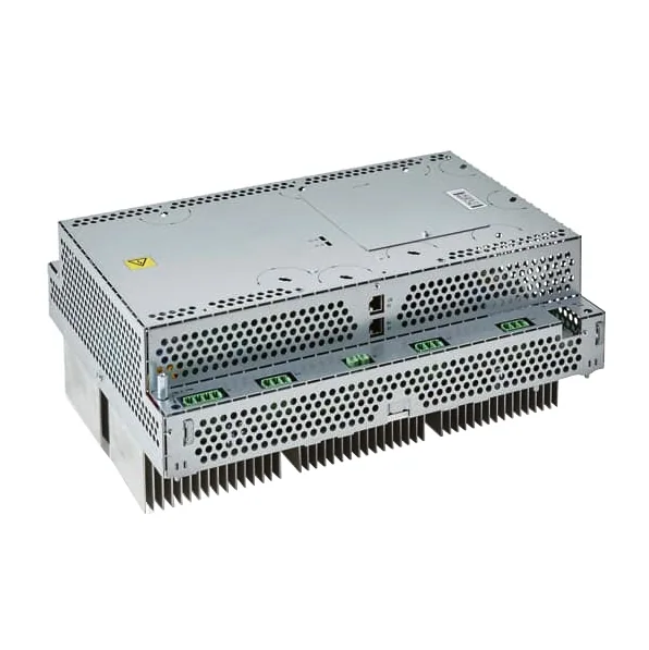
The DSQC663 is commonly found in ABB IRC5 robot control systems, with a common material number of 3HAC029818-001. Configurations may differ between control cabinets and hardware versions. Before inspection or replacement, verify the original module nameplate, complete material number, and corresponding axis group.
1. What are the manifestations of DSQC663 overcurrent faults?
When an overcurrent fault occurs in the DSQC663, the following phenomena may appear:
- Servo cannot be enabled after robot startup.
- Alarm appears the moment the motor is powered on.
- A specific axis suddenly stops during motion.
- Alarm is triggered during robot acceleration or heavy-load operation.
- Normal operation at low speed, but alarm occurs when speed is increased.
- Fault appears when the robot reaches a specific position.
- Alarm temporarily disappears after control cabinet restart, but reappears after running for a period.
- Abnormal temperature rise in the drive.
- Unusual odor or signs of component burning/erosion inside the control cabinet.
The timing and operating conditions when the overcurrent alarm occurs are important clues for determining the fault direction. Alarms occurring immediately upon power-up, during operation, or at specific postures typically correspond to different inspection priorities.
2. Record alarm information before repair
Before troubleshooting, save a complete alarm log to avoid losing important clues due to repeated resets.
It is recommended to record:
- Robot model and body serial number.
- Controller model and system version.
- Complete material number of the DSQC663 module.
- Alarm code, alarm text, and occurrence time.
- Axis number corresponding to the fault.
- Program the robot was executing when the alarm occurred.
- Operating speed, load, and robot posture at the time.
- Whether the fault can be stably reproduced.
- Whether the equipment has recently experienced collisions, repairs, or part replacements.
- Whether the control cabinet fans and ambient temperature are normal.
Do not just record "robot overcurrent." Try to specify whether the alarm occurred during power-up, manual operation, automatic operation, acceleration, deceleration, or at a fixed position.
3. Troubleshooting direction for immediate alarm upon power-up
If an overcurrent alarm appears immediately upon robot startup or servo enable, priority should be given to inspecting the drive, motor power circuit, and related connections.
【Possible Cause One: Power Cable Short Circuit】
Insulation damage on motor power cables, liquid ingress into connectors, burnt pins, or internal cable short circuits may cause the drive to alarm immediately when outputting current.
During inspection, focus on cable sheathing, bending points, connectors, and terminals. When involving insulation and continuity measurements, operate according to the methods specified in the ABB repair manual, and properly isolate the motor, drive, and related circuits to avoid damaging electronic components with test voltages.
【Possible Cause Two: Servo Motor Abnormality】
Motor winding short circuit, abnormal phase-to-phase resistance, insulation degradation, or internal bearing damage can all cause abnormal current.
During testing, compare the status of each phase winding and make judgments based on motor temperature, odor, and operating sound. Measurement methods and acceptable ranges should be based on the technical documentation for the corresponding motor model.
【Possible Cause Three: Internal Fault in Drive Module】
Damage to internal power components, drive circuits, current detection circuits, or power supply sections within the DSQC663 may also cause immediate alarm upon power-up.
If there is a burnt smell, significant dust accumulation, cooling fan failure, or if the module has been exposed to moisture inside the control cabinet, focus inspection on the drive unit itself.
4. Overcurrent alarm occurring during operation
If the robot can be enabled normally but an overcurrent alarm appears after running for a period, focus on checking load, mechanical resistance, temperature rise, and cooling conditions.
【Excessive Mechanical Load】
End-of-arm tooling, gripper, or workpiece weight exceeding the robot's allowable range, or load parameters not matching the actual situation, can cause prolonged high motor current.
In addition to total tool weight, also pay attention to load center of gravity and inertia. Even if the weight is within limits, incorrect center of gravity settings may cause overcurrent during rapid robot acceleration or deceleration.
【Increased Resistance in Robot Body】
When wear, insufficient lubrication, or jamming occurs in reducers, bearings, or mechanical connection points, the motor needs to output higher torque, leading to increased operating current.
Such faults may be accompanied by the following phenomena:
- Single-axis temperature is significantly higher than other axes.
- Unusual noise or vibration during low-speed motion.
- Different resistance during forward and reverse operation.
- Alarm repeatedly occurs at a fixed position.
- Oil leakage or metal grinding noise near the reducer.
【Poor Drive Heat Dissipation】
Control cabinet fan stoppage, clogged filter mats, dust accumulation in air ducts, or excessively high ambient temperature can reduce the DSQC663's heat dissipation capability. After the module temperature rises, its operating state may become unstable.
During troubleshooting, inspect the control cabinet fans, filtration devices, cooling channels, and internal cabinet temperature. Do not only check the drive circuitry.
5. What parts to check for alarms at specific positions
If the robot alarms each time it reaches a similar position or posture, focus on inspecting body cables, external cables, and mechanical interference.
【Body Cable Being Pinched】
When the robot posture changes, internal or external cables continuously bend. If internal conductors are damaged, short circuits or intermittent contact may only occur at certain angles.
【External Cable Being Pulled】
Improper routing of welding torch cables, air hoses, tool cables, or external sensor wiring harnesses may restrict robot movement, causing a sudden increase in motor load.
【Interference from Tooling or Peripheral Equipment】
Slight collisions between the robot, fixture, workpiece, and safety fencing can also cause momentary overcurrent in a specific axis.
Under conditions complying with on-site safety regulations, the fault can be reproduced at low speed while observing robot posture, cable movement, and surrounding tooling conditions. Do not verify the issue by repeatedly running at high speed.
6. How to Distinguish Between Drive, Motor, and Mechanical Faults
【Alarm Occurs Immediately Upon Powering Up and Enabling】
Priority Checks: DSQC663 drive module, motor power cables, and servo motor.
Key Judgment Points: Confirm if the fault occurs before the robot starts moving. Check for cable short circuits, motor windings, and the power section of the drive module.
【Normal at Low Speed, Alarm at High Speed or Under Heavy Load】
Priority Checks: Load parameters, mechanical resistance, servo motor, and drive unit cooling.
Key Judgment Points: Observe if the alarm is related to acceleration, deceleration, load changes, or temperature rise.
【Alarm on a Fixed Axis or at a Fixed Position】
Priority Checks: The axis's own cables, reducer, bearings, and external interference.
Key Judgment Points: Compare performance under different movement directions and speeds. Observe if cables are being pinched in specific postures.
【Normal When Cold, Alarm After Running for a Period】
Priority Checks: Drive unit cooling, motor temperature rise, mechanical friction, and control cabinet temperature.
Key Judgment Points: Record the time from startup to alarm. Check for changes in temperature rise of fans, filters, modules, and motors.
【Fault Persists After Replacing the Drive Unit】
Priority Checks: Motor, power cables, brake, mechanical unit, and load settings.
Key Judgment Points: Re-examine the fault source to avoid repeatedly replacing functional modules.
7. Key Points for Professional DSQC663 Drive Unit Repair
Once the fault is confirmed to be inside the DSQC663, maintenance personnel typically need to inspect the following sections:
Module input power supply section.
Power output devices.
Drive control circuit.
Current sampling and protection circuit.
DC bus-related circuits.
Internal power conversion section.
Connection terminals and solder joints.
Heat sink and temperature detection section.
Whether the circuit board is damp, corroded, or contaminated.
The drive unit contains high-voltage energy storage components. After cutting off the control cabinet power, it is still necessary to wait for the specified discharge time according to the equipment manual and confirm there is no hazardous voltage before proceeding with inspection.
It is not recommended for on-site personnel to force operation by repeatedly powering on, replacing fuse devices, or bypassing protection signals. This may cause further damage to power devices, the motor, or other modules in the control cabinet.
8. What to Verify Before Replacing a DSQC663
If inspection determines the module needs replacement, verify the following:
Module name and complete material number.
Original module hardware version.
Control cabinet model.
Applicable robot and axis group configuration.
Connector and terminal definitions.
Module installation location.
Software and parameter compatibility.
Identical appearance between old and new modules does not guarantee direct interchangeability. It is recommended to photograph the original module's nameplate, installation location, and wiring status, and label all connectors.
During disassembly and assembly, take electrostatic protection measures and do not touch components on the circuit board or interface contacts. After installation is complete, re-check that terminals are locked, wiring is correct, and cooling channels are unobstructed.
9. Common Maintenance Misconceptions
Misconception 1: Replacing the drive unit immediately upon seeing an overcurrent alarm.
Overcurrent alarms can also originate from the motor, cables, and mechanical load. Replacing the module without confirming the fault scope can easily increase repair costs.
Misconception 2: Only checking the electrical section, ignoring mechanical binding.
Resistance caused by reducers, bearings, and external tooling directly increases servo current.
Misconception 3: Repeatedly resetting alarms to continue production.
Intermittent faults may gradually worsen. Repeatedly resetting can destroy the conditions under which the alarm occurs and may also cause more severe damage to the module or motor.
Misconception 4: Neglecting control cabinet cooling.
Clogged filter mats and fan failures simultaneously affect the stable operation of multiple control modules.
Misconception 5: Not recording wiring and module locations.
Failing to photograph, label, and save information before drive unit disassembly can lead to wiring errors or difficulties in subsequent troubleshooting.
10. Post-Repair Verification and Recommissioning
After DSQC663 repair or replacement, verification should proceed in order from low-risk to normal production.
Step 1: Static Inspection
Confirm the module is securely fastened, wiring is correct, terminals are locked, protective covers are reinstated, and clean up any tools or foreign objects left inside the control cabinet.
Step 2: Power-On Inspection
Start the control cabinet and observe for any abnormal sounds, odors, indicator light statuses, or persistent alarms.
Step 3: Low-Speed Single-Axis Test
With the work area confirmed safe, operate the relevant axes separately at low speed. Check for smooth movement and observe for abnormal noise, vibration, or temperature rise.
Step 4: No-Load Coordinated Motion Test
Run the original trajectory or a test program to confirm normal coordinated motion, positioning, and braking status of all axes.
Step 5: Gradually Restore Speed and Load
Gradually increase operating speed, then restore tool and workpiece load. Focus on observing whether alarms reappear during acceleration, deceleration, and posture changes.
Step 6: Process Verification
Use process samples to confirm the robot's positioning accuracy, production cycle time, and work quality.
Step 7: Archive Maintenance Records
Record alarm codes, fault causes, repaired sections, replaced parts, test results, and subsequent maintenance recommendations.
11. Summary
When an ABB robot DSQC663 drive unit shows an overcurrent alarm, start from the conditions under which the alarm occurs and troubleshoot in the order of "alarm log — power circuit — servo motor — mechanical load — cooling system — drive module."
For alarms occurring immediately upon power-up, focus on checking power cables, the motor, and the drive module. For alarms at high speed or under heavy load, check load parameters, mechanical resistance, and temperature rise. For alarms at fixed positions, pay attention to cable bending, external interference, and the mechanical state of the unit itself.
By progressively narrowing down the fault scope, one can reduce incorrect part replacements, improve ABB robot repair efficiency, and lower the probability of equipment downtime recurring.
Repair Consultation
If DSQC663 drive unit repair for ABB robots is required, please provide the robot model, IRC5 controller model, drive module complete material number, alarm code, faulty axis number, and on-site photos or videos of when the alarm occurred. Contact a maintenance engineer for further diagnosis.
Industrial Robot Repair Hotline: +86 18122009539
Contact Maintenance Engineer: +86 18122009539
Need a part or repair assessment?
Share the robot model, part number, fault details and destination country with our team.
Contact our team ↗