
KUKA KR C4 KSP 600-3x40 Drive Fault Repair: Troubleshooting Overcurrent, Overheating, and Inability to Enable
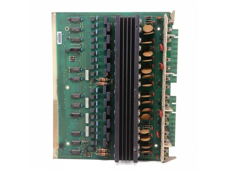
The KSP 600-3x40 servo drive module in the KUKA KR C4 control cabinet is responsible for motor control of multiple robot axes. When the module fails, it may cause the drive to be unable to enable, robot axis group alarms, operational stoppages, overcurrent, or overheating. This article introduces the power supply and control links of the KSP 600-3x40, common fault diagnosis, KPP correlation checks, motor and cable troubleshooting, and methods for restart verification.
In this article
KUKA KR C4 KSP 600-3x40 Drive Fault Repair: Overcurrent, Overheating, and Inability to Enable Troubleshooting
KUKA KR C4 control cabinet drive systems typically consist of a KPP power supply module and KSP servo drive modules working together. The KPP is responsible for providing DC bus power to the drive system, while the KSP is responsible for controlling the servo motors for each robot axis.
The KSP 600-3x40 is a common multi-axis servo drive module within the KR C4 control system. Specific configurations, order numbers, and the controlled axis groups vary depending on the control cabinet and robot model. The module nameplate and electrical diagrams must be verified before any repair.
On-site Diagnostic Conclusions:
If multiple axes cannot be enabled simultaneously, first check the KPP, bus power supply, safety status, and drive bus. If the fault is concentrated on a specific axis corresponding to a KSP, continue checking that axis's motor, power cable, brake, and feedback lines. Do not replace the KSP module solely based on a drive alarm.
Scope of Application:
This article primarily applies to KUKA KR C4 control cabinets and KSP 600-3x40 servo drive modules. Alarm names, module configurations, and inspection requirements should be based on the corresponding KSS version and KUKA technical documentation.
1. Main Functions of the KSP 600-3x40
The KSP servo drive receives motion commands from the control system and controls the torque, speed, and position of each axis based on motor position feedback.
Its operation involves the following parts:
- DC bus power supplied by the KPP.
- Communication between the controller and the drive.
- Power output to the servo motors for each axis.
- Motor position feedback.
- Motor brake control.
- Drive temperature and current protection.
- Control cabinet fans and cooling system.
An abnormality in any of these links can cause the robot drive to fail to enable or stop during operation.
2. Common Manifestations of KSP Faults
When the KSP 600-3x40 malfunctions, the following may occur on-site:
- Robot drive cannot be enabled.
- One or more axes simultaneously display drive alarms.
- Overcurrent fault occurs at the moment of enabling.
- Robot stops suddenly during acceleration or under heavy load.
- Operation is normal when cold, but alarms appear after warming up.
- KSP module temperature is too high.
- A specific robot axis exhibits jitter or discontinuous motion.
- Temporary recovery after control cabinet restart.
- Drive module communication abnormality.
- Burnt smell, discoloration, or abnormal sounds from the module.
Record the axis number corresponding to the alarm and the operational phase when the fault occurred: power-up, enabling, low speed, high speed, or loaded operation.
3. Information to Record Before Repair
Before starting inspection, record the following:
- Complete KUKA robot model.
- KR C4 control cabinet model.
- KSS software version.
- Complete KSP module model and order number.
- Alarm code and complete alarm text.
- Axis number corresponding to the fault.
- Speed and load at the time of the fault.
- Indicator status of KPP and KSP.
- Control cabinet fan and ambient temperature.
- Recent occurrences of collisions, power outages, or module replacements.
- Status of system archives and machine data backups.
Do not just record "drive alarm." The complete alarm text, time of occurrence, and axis number are crucial for determining the fault chain.
4. For Multiple Axes Unable to Enable, Check KPP First
If multiple axes controlled by the KSP cannot be enabled simultaneously, first confirm that the common power supply is normal.
Inspection items include:
- Whether the KPP has completed normal power-up.
- Whether the DC bus can be established.
- Whether connections between KPP and KSP are secure.
- Whether drive bus communication is normal.
- Whether the safety circuit meets enabling conditions.
- Whether the control power supply is stable.
- Whether the KPP has overtemperature or internal faults.
If the KPP does not normally provide bus power, the KSP cannot drive the servo motors even if it is intact.
When measuring the DC bus, use appropriate instruments and testing methods. Dangerous voltages may remain in the control cabinet after power-off; the specified discharge time must be waited.
5. Single-Axis Alarm: Check Motor and Power Cable
If the fault is consistently concentrated on one axis, focus on checking that axis's output chain.
Inspection items include:
- Whether the motor power cable is damaged.
- Whether connectors are loose or burnt.
- Whether there is an abnormality between motor windings.
- Whether the motor insulation status meets requirements.
- Whether the brake can release normally.
- Whether the motor bearings are stuck or making abnormal noises.
- Whether the gearbox has mechanical resistance.
- Whether external tools or cables restrict axis movement.
Motor short circuits, brakes not releasing, and gearbox jamming can all trigger KSP overcurrent protection. Before external faults are ruled out, it is not advisable to directly install a new drive module for testing.
6. Judgment Methods for KSP Overcurrent Faults
【Overcurrent occurs at the moment of enabling】
Priority checks: KSP power output, motor power cable, motor windings, and connectors.
【Overcurrent occurs during motion of a specific axis】
Priority checks: Corresponding axis motor, power cable, mechanical resistance, and gearbox.
【Overcurrent occurs during high speed or acceleration】
Priority checks: Tool load, center of gravity, acceleration, mechanical interference, and motor performance.
【Multiple axes show abnormalities simultaneously】
Priority checks: KPP power supply, bus connections, common communication, and control power supply.
【Overcurrent persists after replacing KSP】
Continue checking: Motor, power cable, brake, mechanical structure, and configuration compatibility.
Drive overcurrent is a protective result and does not necessarily mean the KSP's internal power components are damaged.
7. Judgment Methods for KSP Overheating Faults
KSP overheating can stem from poor control cabinet cooling or prolonged drive overload.
Key inspection points include:
- Whether the control cabinet filter mat is clogged.
- Whether the fans are rotating normally.
- Whether the air intake and exhaust vents are blocked.
- Whether the module heat sink is dusty.
- Whether the control cabinet door is properly closed.
- Whether the ambient temperature is too high.
- Whether the motor and mechanical load are abnormal.
- Whether the internal temperature detection circuit of the KSP is normal.
If the robot operates normally in a cold state but triggers an alarm after a fixed period, record the time from startup to the alarm, and check the control cabinet temperature, KSP temperature rise, and airflow changes.
Do not use keeping the control cabinet door open long-term as a cooling method. Opening the cabinet door disrupts the original airflow path and increases the risk of dust, oil, and metal debris entering.
8. KSP Communication Fault Troubleshooting
KSP needs to maintain normal communication with the control system and other drive modules. Communication abnormalities may cause multiple axes to stop or drives to fail to enable.
Check:
- Whether the drive bus connectors are loose.
- Whether the communication cables between modules are damaged.
- The communication status between KPP and KSP.
- Whether the control power supply is stable.
- Whether the module addresses and configuration are correct.
- Whether the replacement module matches the original system configuration.
- Whether there is oxidation, liquid ingress, or contamination at the interfaces.
If the fault occurs after the control cabinet has been subjected to vibration, focus on checking connectors and interface solder joints.
9. Why Brake Faults Can Cause Drive Alarms
After the robot axis servo is enabled, the brake needs to release according to the control logic. If the brake does not fully open, the motor must overcome additional resistance, which may cause a rapid current increase.
Common manifestations include:
- Difficulty starting the axis.
- Humming sound after enabling.
- Unsteady low-speed operation.
- Rapid motor temperature rise.
- KSP showing overcurrent or overload alarms.
- Significantly increased resistance in a specific movement direction.
During inspection, confirm the brake power supply, connection wiring, and mechanical condition. Do not directly apply external voltage to the brake without understanding the wiring definitions.
10. Relationship Between Mechanical Load and Drive Alarms
Incorrect tool weight, center of gravity, and inertia settings cause the controller's calculated axis torque to be inconsistent with the actual load.
The following situations can easily cause drive faults:
- Failing to update load data after changing tools.
- Workpiece weight exceeding the original setting.
- Tool center of gravity being too far from the flange.
- Welding torch cables or air hoses pulling on the robot.
- Increased resistance in reducers and bearings.
- Mechanical interference between the robot and the fixture.
- Motion speed or acceleration settings being too high.
If operation is normal under no load but alarms occur under load, first verify the tool and workpiece loads, then check mechanical resistance and motor output.
11. Common Internal Repair Areas of KSP Modules
After confirming the fault is inside the KSP, professional repair typically requires inspecting:
- DC bus input section.
- Power output devices.
- Gate drive circuit.
- Current sampling circuit.
- Internal switching power supply.
- Temperature detection and protection circuit.
- Drive bus communication section.
- Connectors and interface solder joints.
- Heat sink and thermal conduction structure.
- Whether the circuit board is damp, corroded, or contaminated.
KSP contains high-voltage power circuits. Internal inspection and component replacement should be performed by personnel with relevant experience.
12. What to Verify Before Replacing a KSP
Before replacing a module, verify:
- The complete KSP model number.
- Module order number.
- Hardware version.
- Control cabinet model.
- Module installation position.
- Controlled axis group.
- Interface and terminal configuration.
- KSS version and system compatibility.
- Original module wiring and installation status.
KSP modules with similar appearances may not be directly interchangeable. Before disassembly, photograph the nameplate, wiring, and installation position, and label the connectors.
13. KSP Fault Repair Procedure
Step 1: Save alarm records and module indicator status.
Step 2: Record robot, KR C4 control cabinet, and KSS versions.
Step 3: Back up machine data and system archives.
Step 4: Confirm safety circuit and control power supply.
Step 5: Check KPP and DC bus power supply.
Step 6: Identify the axis group corresponding to the fault.
Step 7: Check motor, power cables, brake, and mechanical load.
Step 8: Check drive bus and KSP heat dissipation.
Step 9: Repair or replace the confirmed faulty KSP module.
Step 10: Complete safety function, single-axis, no-load, and load verification.
14. Post-Repair Restart Verification
After completing repairs, check in sequence:
- Whether modules and connectors are securely installed.
- Whether tools or foreign objects remain inside the control cabinet.
- Whether grounding, protective panels, and control cabinet doors are restored to normal.
- Whether KPP and KSP indicator statuses are normal.
- Whether the control system has any persistent alarms.
- Whether emergency stop, safety door, and confirmation switches are effective.
- Whether each axis operates smoothly at low speed in both directions.
- Whether there is abnormal temperature rise in motors and KSP.
- Whether no-load multi-axis coordinated motion programs run normally.
- Whether actual tool operation under load is stable.
- Whether the position and quality of process samples are acceptable.
After restart, run continuously for a period to confirm that overcurrent, overheating, or communication alarms do not reappear.
15. Common Questions
Does KSP overcurrent always mean the drive is damaged?
Not necessarily. Motor short circuits, damaged power cables, brakes not releasing, and mechanical jams can all trigger overcurrent protection.
What should be checked first if multiple axes fail to enable simultaneously?
First check the safety status, KPP, DC bus, and common communication link.
Can production resume directly after replacing a KSP?
It is necessary to confirm model and configuration compatibility and complete safety function, low-speed single-axis, no-load coordinated motion, load, and process tests.
Can opening the control cabinet door solve overheating?
It should not be used as a long-term solution. Check fans, filter mats, airflow paths, ambient temperature, and module load.
16. Summary
When the KUKA KR C4's KSP 600-3x40 experiences overcurrent, overheating, or inability to enable, the first step is to determine whether the fault lies in the common power supply, multi-axis drive, or single-axis output circuit.
Simultaneous abnormalities in multiple axes should focus on checking the KPP, DC bus, and drive bus; single-axis faults should check the motor, power cable, brake, and mechanical load; if an alarm occurs after running for a period, priority should be given to inspecting the control cabinet cooling and module temperature rise.
Technical content reference: KUKA KR C4 drive system structure, KSP technical documentation, and industrial robot on-site repair experience
Content update time: September 2026
Repair Consultation
If repair is needed for the KUKA KR C4 control cabinet, KSP 600-3x40, KPP module, or servo motor, please provide the robot model, control cabinet model, KSS version, complete alarm information, module nameplate, and on-site photos.
Industrial Robot Repair Hotline: +86 18122009539
Contact Repair Engineer: +86 18122009539
Need a part or repair assessment?
Share the robot model, part number, fault details and destination country with our team.
Contact our team ↗