
Case Study: ABB IRB 6640 Triggers Collision Alarm During High-Speed Operation, Troubleshooting and Replacement of Axis 2 Reducer
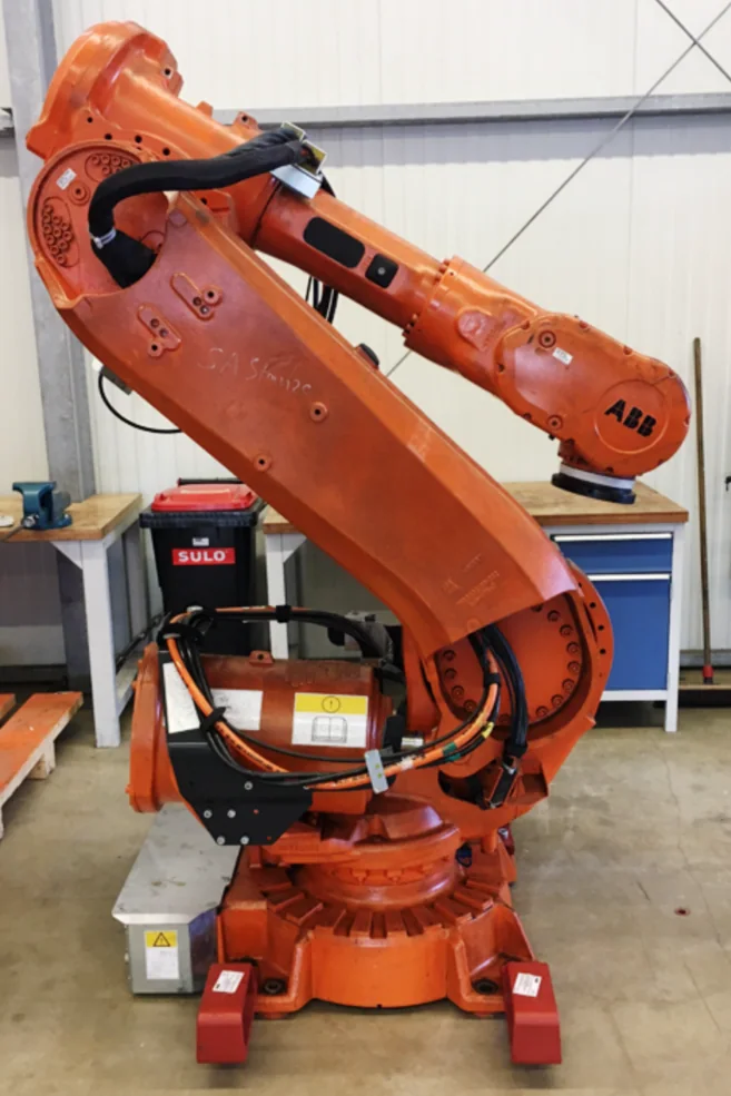
An ABB IRB 6640 robot at an automotive parts company in Chongqing could operate at low speeds, but frequently triggered collision alarms when speed was increased. The Axis 2 servo motor and lubricating oil had been replaced previously, but the fault persisted. Further on-site inspection revealed abnormal oil condition and significant debris in the Axis 2 reducer, with noticeable sticking during no-load rotation. The Axis 2 reducer unit was ultimately confirmed as faulty.
In this article
Maintenance Case: ABB IRB 6640 High-Speed Operation Triggers Collision Alarm, Fault Diagnosis and Replacement of Axis 2 Reducer
This case involves an ABB IRB 6640 industrial robot used by an automotive parts manufacturer in Chongqing. The customer reported that the robot could still operate, but increasing the operating speed would trigger a collision alarm, causing production program interruptions.
Before contacting Zhongheng Biao maintenance engineers, on-site maintenance personnel had already replaced the Axis 2 servo motor and treated the Axis 2 lubricating oil, but the fault persisted.
Through analysis of on-site videos, alarm information, and robot operating status, the maintenance engineer preliminarily determined that the fault was not from the newly replaced servo motor, but rather a mechanical abnormality inside the Axis 2 reducer.
Case file number: 24422.
1. Fault phenomena reported by the customer
The main robot faults manifested as:
- Can still operate at low speeds.
- Triggering a collision alarm after increasing the operating speed.
- The fault is mainly related to Axis 2 movement.
- The fault did not disappear after replacing the Axis 2 servo motor.
- The alarm persists even after replacing or treating the lubricating oil.
- The robot cannot restore its original production speed.
This fault has a clear speed correlation. During low-speed operation, motor output and mechanical impact are smaller, and internal jamming in the reducer might not immediately trigger monitoring; after increasing speed, axis movement resistance and actual position deviation increase, and the system may identify it as a collision or movement abnormality.
2. Previously taken actions
The customer had previously contacted local maintenance personnel for inspection and took the following measures:
- Replaced the Axis 2 servo motor.
- Checked the Axis 2 operating status.
- Replaced or treated the Axis 2 lubricating oil.
After these actions, the robot still triggered a collision alarm during high-speed operation.
This indicates that the fault cannot continue to be judged solely based on the motor and lubricating oil; further inspection of the Axis 2 mechanical transmission system is required.
3. Preliminary remote judgment
The maintenance engineer conducted a preliminary analysis based on the information provided by the customer.
The main basis includes:
- A clear relationship between the fault and operating speed.
- Alarms concentrated during Axis 2 movement.
- No change in phenomena after replacing the servo motor.
- Simply treating the lubricating oil did not restore the mechanical state.
- The robot can still operate at low speeds, indicating Axis 2 is not completely locked.
Combining these phenomena, the initial focus of troubleshooting shifted to the Axis 2 reducer, internal bearings, and mechanical transmission resistance.
4. Why a reducer fault triggers a collision alarm
ABB robots monitor each axis during movement based on command position, actual feedback, drive torque, and motion status.
If internal jamming occurs in the Axis 2 reducer, it may cause:
- Abnormal increase in motor output torque.
- Actual axis position cannot normally follow commands.
- Sudden changes in resistance during high-speed movement.
- Impacts during acceleration and deceleration phases.
- The control system judges that the robot is subjected to external force or has collided.
Therefore, a collision alarm does not necessarily mean the robot actually hit the tooling; it could also be caused by the reducer, bearings, brake, or other mechanical resistance.
5. Preparations before on-site inspection
The Axis 2 of the robot bears the combined load of the arm, wrist, and tool. Support and hoisting preparations are needed before disassembly and inspection.
On-site preparations include:
- Confirming the robot and surrounding equipment are stopped.
- Backing up the current robot system and programs.
- Saving alarm records and related parameters.
- Cleaning the maintenance area around the robot.
- Preparing lifting and transport equipment.
- Preparing screwdrivers, wrenches, and disassembly tools.
- Preparing lubricants, sealing materials, and cleaning supplies.
- Marking each connection point and installation direction of the robot.
- Performing power-off, lockout, and tagging.
During maintenance, the robot arm cannot be supported solely by the Axis 2 motor brake; reliable mechanical support and lifting devices must be used.
6. Confirmation of robot operating status
Before disassembly, maintenance personnel first performed a power-on check on the robot and confirmed:
- Current robot system status.
- Axis 2 alarm information.
- Axis 2 low-speed movement performance.
- Servo motor operating status.
- Robot posture when the fault occurs.
- Whether the alarm can be reproduced after increasing the operating speed.
Reproducing the fault before maintenance establishes a baseline for comparison before and after reducer replacement.
7. System and parameter backup
A backup of the IRC5 system was performed before mechanical disassembly.
Main backup contents include:
- Robot programs.
- System parameters.
- Tool data.
- Workpiece coordinates.
- Load data.
- Revolution counter information.
- Calibration data.
- I/O and communication configurations.
Backing up robot data helps check the Axis 2 calibration status after maintenance and avoids parameter or program loss during disassembly.
8. Robot relocation and hoisting
To inspect and replace the Axis 2 reducer, the robot was relocated on-site.
Main operations include:
- Removing robot base fasteners.
- Using lifting equipment to hoist the robot.
- Confirming robot center of gravity and hoisting status.
- Using transport equipment to move the robot to the maintenance area.
- Placing the robot stably with reliable support.
The IRB 6640 body is heavy; hoisting requires confirming that lifting equipment, lifting points, slings, and transport paths meet requirements.
9. Axis 2 reducer oil inspection
During disassembly, maintenance personnel drained and inspected the internal oil of the Axis 2 reducer.
The inspection found:
- Abnormal oil condition.
- Significant debris in the oil.
- Obvious oil deterioration.
The presence of abnormal debris in the reducer oil may be related to wear of internal gears, bearings, or other transmission components.
Simply replacing the lubricating oil can only remove some contaminants; it cannot repair existing gear wear, bearing damage, or internal jamming.
10. No-load rotation test
After disassembling the axis-2 gear unit, the maintenance personnel performed a no-load rotation check on the gear unit.
The test revealed:
- The gear unit rotation exhibited noticeable sticking.
- The rotation range was limited.
- The rotatable angle was less than 75 degrees.
- The rotation condition did not meet normal mechanical requirements.
This test result indicates that the fault originates from the internal mechanical parts of the gear unit, not from servo motor control parameters or the drive module in the control cabinet.
Combined with the abnormal oil condition, internal debris, and mechanical sticking, it was ultimately confirmed that the axis-2 gear unit assembly needed replacement.
11. Final Fault Diagnosis
This fault was ultimately diagnosed as:
Abnormal internal mechanical condition of the ABB IRB 6640 axis-2 gear unit, causing sticking during rotation, which led to increased axis-2 motion resistance and servo load during high-speed operation, subsequently triggering the robot collision monitoring.
Replacing the axis-2 servo motor earlier did not solve the problem because the motor was not the primary faulty component.
The fault persisted after changing the lubricating oil because the gear unit had already sustained internal mechanical damage; lubrication maintenance cannot substitute for mechanical repair.
12. Pre-installation Inspection of the New Gear Unit
Before replacing the axis-2 gear unit, maintenance personnel need to confirm:
- The new gear unit model matches the original equipment.
- The gear unit mounting surface is clean.
- The positioning structures are not damaged.
- The condition of related bearings and connecting components is normal.
- Seals and sealing materials meet requirements.
- Lubricant material and fill quantity are correct.
- Motor installation and connection positions are normal.
- All disassembled components have been properly marked for position.
- Lifting and mechanical supports remain reliable.
Do not select a gear unit based solely on the robot model; also confirm using the body serial number, original gear unit nameplate, and part number.
13. Axis-2 Gear Unit Replacement Process
The gear unit replacement mainly includes:
Step 1: Adjust the robot to a suitable maintenance position for disassembly/assembly.
Step 2: Reliably support the robot arm and related structures.
Step 3: Disconnect and mark related motor and feedback connections.
Step 4: Drain the internal oil from the gear unit.
Step 5: Disconnect axis-2 connecting components in the specified order.
Step 6: Remove the old gear unit with sticking.
Step 7: Clean the mounting surface and inspect positioning structures.
Step 8: Install the new, model-matched gear unit.
Step 9: Reinstall the servo motor, connecting parts, and related wiring.
Step 10: Complete lubrication, sealing, and tightening according to equipment requirements.
During installation, avoid impacting the gear unit's input end, output end, and precision positioning surfaces.
14. Why Installation Position and Orientation Must Be Marked
Disassembly/assembly of the axis-2 gear unit involves multiple connecting components, positioning structures, and wiring.
Marking in advance can prevent:
- Incorrect gear unit installation orientation.
- Confusion of connecting component positions.
- Incorrect connection of motor and feedback wiring.
- Significant deviation of the mechanical zero position.
- Omission of sealing and lubrication points.
- Increased subsequent calibration workload.
Taking clear photos before disassembly can serve as an important reference during reassembly.
15. Post-installation Mechanical Inspection
After installing the new gear unit, static and low-speed inspections should be performed first.
Inspection content includes:
- Whether the gear unit installation is secure.
- Whether connecting bolts are tightened as required.
- Whether motor and feedback wiring are correctly connected.
- Whether mechanical supports can be safely removed.
- Whether axis-2 can rotate smoothly.
- Whether the rotation range has returned to normal.
- Whether there are new friction noises or sticking.
- Whether there is leakage at the gear unit seal locations.
High-speed production programs should not be executed directly before confirming normal mechanical installation.
16. Calibration and Position Confirmation
After replacing the axis-2 gear unit, the robot's calibration status needs to be confirmed.
Inspection content includes:
- Axis-2 mechanical zero position marks.
- Revolution counter status.
- Teach pendant displayed angle.
- Historical calibration data.
- Known reference points.
- Tool TCP.
- Workpiece coordinates.
If the mechanical positional relationship has changed, calibration or revolution counter updates should be performed according to the ABB manual for the corresponding model.
Do not substitute correct mechanical calibration by modifying production program points.
17. Post-repair Restart Verification
After completing this gear unit replacement, the robot underwent operational testing on-site to confirm the equipment could resume normal operation.
Standard restart verification should include:
- Reviewing current and historical alarms.
- Low-speed operation of axis-2 in forward and reverse directions.
- Checking for any remaining sticking at different angles.
- Checking for impact during direction changes.
- Executing low-speed multi-axis coordinated motion programs.
- Gradually increasing robot operating speed.
- Restoring actual tool and workpiece loads.
- Observing axis-2 motor and gear unit temperature rise.
- Checking if the robot triggers collision alarms again.
- Verification using actual process programs.
Only when high-speed, loaded, and process operations are all normal can the fault resolution be confirmed as complete.
18. Repair Outcome of This Case
After completing the axis-2 gear unit replacement and assembly, the robot resumed normal operation.
The results of this repair indicate:
- The original axis-2 servo motor was not the primary fault source.
- The axis-2 gear unit had mechanical sticking.
- Abnormal oil condition and internal debris reflected mechanical wear issues.
- Simply replacing lubricating oil cannot eliminate internal damage.
- After replacing the axis-2 gear unit, the robot passed operational testing.
19. Key Diagnostic Points of This Case
This case has the following reference value:
First, a collision alarm does not necessarily mean the robot experienced an external collision.
Second, when operation is normal at low speed but alarms occur at high speed, mechanical resistance and gear unit condition should be checked.
Third, if the fault remains unchanged after replacing the servo motor, the mechanical transmission section should be re-evaluated.
Fourth, abnormal debris in the oil can serve as a clue for judging internal wear in the gear unit.
Fifth, no-load rotation testing can help confirm if the gear unit is sticking.
Sixth, after repair completion, verification must be performed restoring high speed and actual loads.
20. Daily Maintenance Recommendations
- Regularly check the oil condition of the Axis 2 reducer.
- Observe if there are any abnormal foreign particles in the oil.
- Record the operating sound and temperature changes of Axis 2.
- Pay attention to differences between low-speed and high-speed operation.
- Save complete fault records after a collision alarm occurs.
- Avoid prolonged operation beyond the set load.
- Check the mechanical condition of Axis 2 after a robot collision.
- Do not continue high-speed production by repeatedly resetting alarms.
21. Summary
An ABB IRB 6640 robot at an automotive parts company in Chongqing frequently triggered collision alarms during high-speed operation. The fault persisted even after replacing the Axis 2 servo motor and handling the lubricating oil on-site.
Further disassembly and inspection revealed abnormal oil quality and a significant amount of debris in the Axis 2 reducer. Unloaded rotation showed sticking and limited rotation range. The robot was ultimately restored to normal operation by replacing the Axis 2 reducer and completing assembly and running tests.
Case reference: Zhongheng Biao Robot Repair Knowledge Base, Article No. 24422
Repair Consultation
If encountering ABB IRB 6640 robot high-speed collision alarms, Axis 2 sticking, or reducer abnormal noise, please provide the robot's complete model, IRC5 version, alarm screen, operating speed, faulty axis number, and on-site video.
Industrial Robot Repair Hotline: +86 18122009539
Contact Repair Engineer: +86 18122009539
Need a part or repair assessment?
Share the robot model, part number, fault details and destination country with our team.
Contact our team ↗