
ABB Robot Repair for Repeated IRC5 Main Switch Trips
A structured ABB IRC5 diagnostic process for repeated main switch trips, covering fault records, external loads, cabinet inspection, and repair decisions.
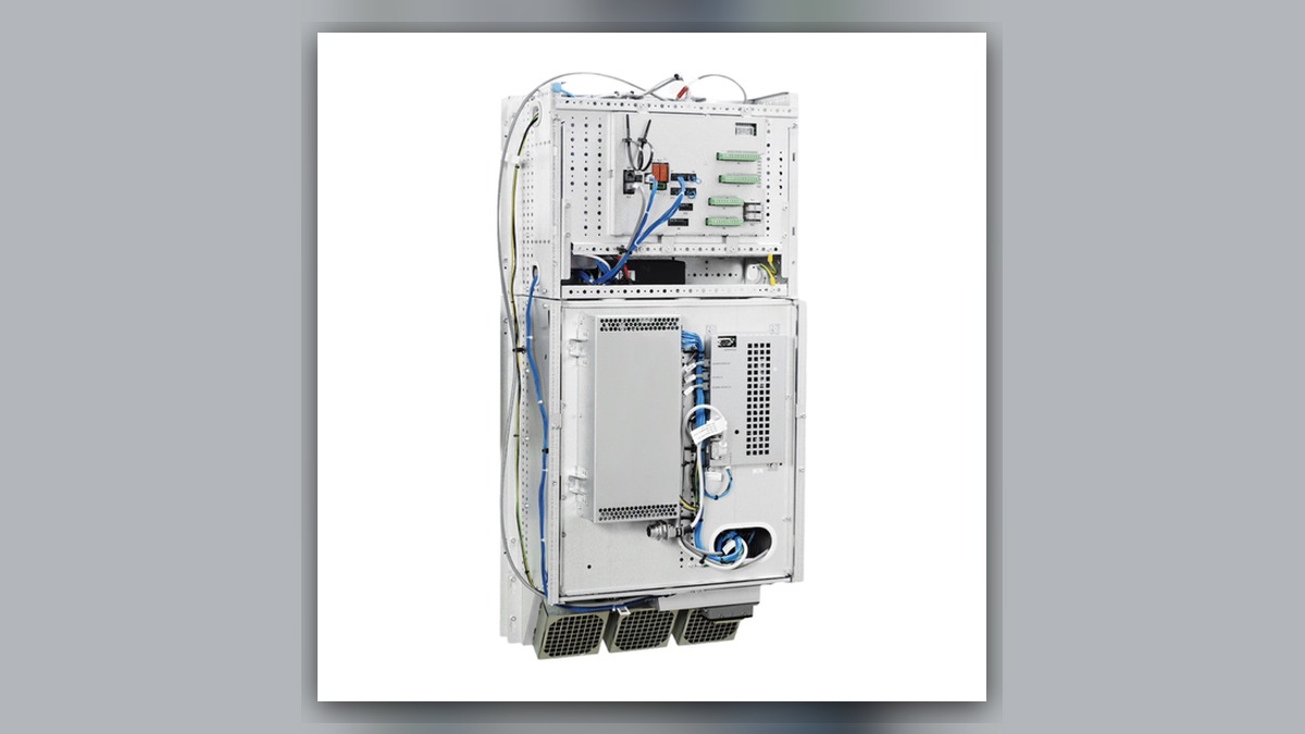
Repeated main switch tripping on an ABB IRC5 controller requires a controlled ABB robot repair investigation covering the incoming supply, cabinet wiring, connected loads, contamination, cooling condition, and internal power components. Before resetting anything, record the complete event text, trip timing, operating state, robot position, and any recent cabinet work. A tripped switch does not independently prove that the switch, drive unit, power supply, or servo motor is defective. The trip may be a protective response to a fault elsewhere in the installation.
Symptoms and Scope
This diagnostic approach applies to ABB robot systems using an IRC5 controller when the cabinet main switch trips, will not remain set, or trips again during startup or operation. The installed controller variant, robot model, options, external axes, and connected equipment must be identified before component-level inspection.
The article does not establish a universal cause for every protective-device operation. Site distribution equipment, upstream protection, machine wiring, peripheral equipment, and controller configurations vary. An upstream circuit breaker opening is also not necessarily the same condition as the IRC5 cabinet main switch tripping. Record exactly which device operated.
Information to Record First
Preserve the evidence before attempting another startup. Alarm history and operating conditions can show whether the event occurred during controller power-up, motor enable, robot motion, tool operation, or an unrelated machine sequence.
Complete alarm code and full text:
Date and exact time:
Faulted axis:
Robot position/posture:
Program step or motion:
Actual speed and load condition:
Reset result:
Time until recurrence:
Related power, communication or feedback alarms:
Also record the robot model, IRC5 controller type, controller serial information, main switch identification, installed drive units, external axes, and recently replaced parts. Note whether electrical work, cleaning, production changes, a collision, or liquid exposure preceded the event. Do not repeatedly reset a protective device merely to reproduce the trip.
Safety and Preparation
Only suitably qualified personnel should access the controller. Follow the applicable ABB documentation, site lockout and tagout procedure, and local electrical safety requirements. Isolate all relevant energy sources and verify the required safe state before opening the cabinet or handling connections.
Do not bypass a breaker, fuse, interlock, or protective conductor. Do not increase protective-device ratings to keep the robot operating. Unsupported live measurements, insulation tests through connected electronics, and uncontrolled disconnection of internal wiring can create hazards or damage equipment. Any electrical test must be selected and performed by competent personnel using the applicable controller documentation and correctly rated instruments.
ABB Robot Repair Diagnostic Sequence
- Identify the operated protective device. Determine whether the cabinet main switch, an upstream distribution breaker, or protection associated with peripheral equipment opened. Record its label and visible trip indication. If the device cannot be positively identified, stop and obtain the electrical drawings and cabinet configuration information before proceeding.
- Review when the trip occurred. A trip immediately after the main switch is set presents a different diagnostic branch from one that occurs after motor power is requested or only during motion. A trip associated with a tool command may direct attention toward peripheral loads rather than the robot drive system. Timing narrows the inspection scope but does not confirm the failed component.
- Inspect the external supply path. With the system safely isolated, qualified personnel should examine accessible supply cables, terminals, disconnect equipment, protective devices, and protective-earth connections for looseness, discoloration, contamination, or visible damage. Confirm that the installed supply arrangement agrees with the machine documentation. Missing supply specifications or undocumented modifications must be resolved before further testing.
- Check cabinet condition. Inspect for water, coolant, oil, conductive dust, loose hardware, damaged insulation, overheated connectors, blocked airflow, and evidence of previous repair. Do not energize equipment with unresolved contamination or visible insulation damage. Photograph abnormal findings before cleaning or disturbing them.
- Separate controller loads methodically. Use the applicable ABB procedure and electrical drawings to determine which internal or external load groups can be safely isolated for diagnosis. The decision must account for controller options and external axes. Randomly unplugging assemblies can introduce communication faults, lost configuration evidence, connector damage, or unsafe machine states.
- Evaluate the relevant assembly. If the evidence consistently places the trip in an internal controller branch, the associated drive unit, power supply, wiring, connector, or other assembly may require professional bench inspection. If the event occurs only when a particular axis is enabled, inspect that axis branch without assuming the servo motor is defective. Motor power cables, connectors, drive electronics, and mechanical loading may also require evaluation.
How to Distinguish Similar Causes
An immediate trip before the controller completes startup may indicate a fault in the incoming-power path or an energized controller load, but the exact branch depends on the installed configuration. A trip when motor power is requested shifts attention toward the drive power stage and connected motor circuits. A trip only during a specific command may involve an axis, external axis, or peripheral load activated at that point.
Visible heat damage identifies an inspection location, not necessarily the initiating cause. Likewise, a switch that has operated several times is not automatically defective. The switch may be responding correctly to an excessive-current or insulation-related condition that must be located before replacement is considered.
When Repair or Replacement May Be Considered
Repair or replacement becomes reasonable only after inspection evidence isolates an assembly and verifies that connected wiring and loads will not immediately damage a repaired unit. Any replacement must match the exact ABB part number, hardware revision, electrical rating, connector layout, controller variant, and installed options. Configuration and backup requirements should be established before removing an electronic assembly.
For a structured IRC5 controller assessment, see https://autonews.best/products/abb-irc5-kong-zhi-gui-yu-ji-xiu. ZHB is an independent industrial robot inspection, repair, and maintenance service provider that also supplies parts to overseas customers; it does not imply ABB manufacturer authorization.
Verification After Repair
Before controlled restart, confirm that tools, temporary jumpers, disconnected grounds, and test equipment have been removed or restored correctly. Verify cabinet connections, covers, cooling paths, protective devices, backups, and safety-system status according to the applicable documentation.
Qualified personnel may then perform a staged restart under controlled conditions and the site safety procedure. Check controller startup, alarm history, motor enable, low-risk axis movement, and the original operating stage without deliberately creating an electrical fault. Record whether the protective device remains set and whether any related alarm returns. Production release should also include verification of robot operation, peripheral interlocks, and safety functions affected by the work.
Information Required for a Repair Inquiry
For an industrial robot repair service inquiry, provide the robot model, IRC5 controller model, complete alarm code and text, alarm history, component label, fault conditions, and clear photographs of the cabinet, operated protective device, and any visible damage. Include the event timing, whether the trip occurs at power-up, motor enable, motion, or tool activation, plus details of recent maintenance or electrical changes. This information supports safer triage and reduces the risk of sending an unrelated component for repair.
Conclusion
Repeated IRC5 main switch trips should be treated as a protective event requiring evidence-based diagnosis. Identify the device that operated, preserve the event history, inspect external power and cabinet condition, and isolate the affected load branch using the correct configuration documents. Component repair or replacement should follow fault isolation, not precede it.