
Yaskawa SGDM-20ADA-V Drive Overcurrent, Overload, and Encoder Alarm Repair
When a Yaskawa SGDM-20ADA-V servo drive experiences overcurrent, overload, feedback abnormalities, or stops during operation, troubleshooting should follow the sequence of power supply, motor, encoder, and load.
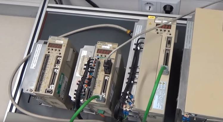
The SGDM-20ADA-V is used in Yaskawa Sigma-II servo systems. Overcurrent or overload alarms can be caused by internal drive abnormalities, or by factors such as decreased motor insulation, short circuits in power lines, or mechanical jamming.
The key to on-site diagnosis is first determining the fault scope, then deciding on the repair target. During the inspection process, record alarms, axis numbers, robot posture, and recurrence conditions to avoid replacing components based solely on a single alarm.
- Common Fault Manifestations
- Overcurrent occurs at power-on or enable instant.
- Overload occurs during equipment acceleration or under load.
- Encoder alarm accompanied by position fluctuations.
- Stops after running for a period due to temperature abnormalities.
- Possible Causes
- Phase-to-phase or phase-to-ground short circuit in motor power lines.
- Abnormalities in motor windings, brake, or encoder.
- Excessive load inertia, mechanism jamming, or unsuitable parameters.
- Control cabinet temperature too high or air ducts blocked.
- Aging of drive power module, detection circuit, or capacitors.
- On-site Troubleshooting Sequence
- Record whether the alarm occurs during power-on, enable, acceleration, or stable operation.
- Check power line insulation, connectors, and motor condition.
- Check encoder cable, grounding, and shielding.
- Check mechanical load, couplings, and drive parameters.
- After confirming external conditions are normal, proceed with drive repair or replacement.
- Verification Before Replacing Components
Verify the complete SGDM-20ADA-V model number, capacity, input power, control interface, matching motor, and original parameters to avoid capacity or control method mismatches.
Similar external appearance does not mean direct replacement is possible. Before procurement, provide the complete equipment model number, original component nameplate, interface photos, controller model, and alarm information.
- Post-repair Restart Verification
After clearing alarms, perform no-load, low-speed, acceleration/deceleration, and loaded operation sequentially, and record current, temperature rise, and positioning results.
After repair completion, also save test results, replaced component part numbers, and final parameters to facilitate tracking by subsequent maintenance personnel.
- Summary
When handling such faults, troubleshoot in the order of alarm records, power supply and connections, feedback lines, mechanical load, and the component itself. Only after external conditions are confirmed normal can you further determine if the target component requires repair or replacement.
Industrial Robot Repair Hotline: +86 18122009539
Contact Repair Engineer: +86 18122009539