
How to Handle FANUC A290-0561-V503 Encoder Alarm? Methods for Position Feedback and Zero Point Recovery
When the FANUC A290-0561-V503 encoder experiences feedback loss, position abnormality, or servo enable failure, it is necessary to simultaneously check the encoder, battery, feedback cable, and mechanical installation.
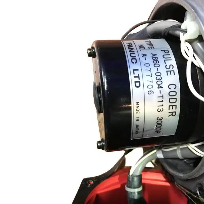
The encoder is responsible for providing position feedback of the motor shaft to the servo system. After an abnormality occurs with the A290-0561-V503, it may cause position data loss, axis vibration, servo enable failure, or zero point offset.
The key to on-site diagnosis is to first determine the fault scope, then decide on the repair target. During the inspection process, record alarms, axis numbers, robot posture, and recurrence conditions to avoid replacing components based solely on a single alarm.
- Common Fault Manifestations
- The controller indicates encoder or feedback communication abnormality.
- The motor can rotate but position data is unstable.
- Zero point or position data loss occurs after robot power-off.
- Single-axis vibration, positioning deviation, or fixed posture alarm.
- Possible Causes
- Loose encoder connector, bent pins, or oil ingress.
- Broken core or damaged shielding in the feedback cable.
- Insufficient backup battery voltage for the encoder.
- Encoder installation deviation or loose mechanical connection.
- Damaged electronic components in the encoder body.
- On-site Troubleshooting Sequence
- Record alarm codes, faulty axis, and zero point status.
- Check the encoder connector, feedback cable, and battery voltage status.
- Check the motor tail installation, connecting parts, and fixing screws.
- Perform cable or encoder cross-verification in accordance with manual requirements.
- After replacement, perform position confirmation and zero point recovery according to the corresponding control system.
- Verification Before Replacing Components
Before ordering, verify the complete motor model, original encoder number, interface, installation dimensions, and hardware version; save the robot zero point and calibration data before disassembly.
Similar appearance of models does not mean they can be directly replaced. Before procurement, provide the complete equipment model, original component nameplate, interface photos, controller model, and alarm information.
- Post-Repair Restart Verification
After completing zero point recovery, move the faulty axis at low speed, checking current position, mechanical markings, movement direction, TCP, and original program trajectory.
After repair completion, also save test results, replacement component numbers, and final parameters to facilitate tracking by subsequent maintenance personnel.
- Summary
When handling such faults, troubleshoot in the order of alarm records, power supply and connections, feedback lines, mechanical load, and the component itself. Only after external conditions are confirmed normal can further judgment be made on whether the target component needs repair or replacement.
Industrial Robot Repair Hotline: +86 18122009539
Contact Repair Engineer: +86 18122009539