
KUKA KR C4 Compact Interface Board 00-188-971 Fault Repair: Troubleshooting 27V Power Supply, US1/US2, and I/O Abnormalities
When a fault occurs on the KUKA KR C4 Compact control cabinet interface board 00-188-971, it may cause abnormalities in the 27V control power supply, loss of US1/US2 power supply, I/O modules going offline, interruption of peripheral signals, or the robot failing to start normally. This article introduces troubleshooting methods for the interface board's power supply, connectors, external loads, and the board itself.
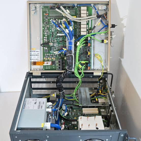
The KUKA KR C4 Compact control cabinet distributes operating power to the controller, I/O, and peripheral devices through internal power supplies, interface boards, and connecting cables. After an abnormality occurs in the 00-188-971 interface board or related power supply lines, it may cause some modules to lose power, peripheral signals to be lost, robot startup to be interrupted, or the system to repeatedly alarm.
On-site diagnostic conclusion: Before testing the 00-188-971 interface board, the upstream power supply and downstream loads should be checked first. Short circuits in external wiring, damaged sensors, poor connector contact, or abnormal load currents can all pull down the US1, US2, or related 27V power supplies, causing a normal interface board to exhibit fault symptoms.
1. Confirm Control Cabinet and Board Model
Check the control cabinet nameplate to confirm the equipment belongs to the KR C4 Compact series, then verify the complete material number, hardware version, and connector markings on the interface board. Different batches or alternative versions of 00-188-971 may have configuration differences; confirm with electrical drawings before repair and replacement.
2. Main Functions of the Interface Board
The 00-188-971 interface board is used for power and signal connections inside the KR C4 Compact control cabinet. Board markings typically involve interfaces such as 27VDC, US1, US2, and X56Int. Its main function is to connect the upstream control power supply with downstream modules or peripheral circuits. The specific terminal functions should be based on the corresponding control cabinet electrical drawings.
3. Common Fault Manifestations
Common phenomena include some modules having no status indication after the control cabinet starts, I/O devices going offline, all sensor signals being lost, peripheral valve groups not actuating, US1 or US2 power supply abnormalities, and the controller repeatedly alarming during the startup process. Some faults temporarily resolve after disconnecting external loads.
4. Record Alarms and Indicator Status
Before inspection, record the complete alarm content on the smartPAD, the time of occurrence, and the control cabinet startup phase. Simultaneously, photograph the indicator status of the interface board, power supply modules, and related equipment. It is necessary to confirm whether the fault is concentrated in a specific I/O group, a specific power branch, or affects the entire control system.
5. Check Upstream Input Power Supply
First, confirm the control cabinet input power and internal control power supplies are normal, then measure whether the power reaching the interface board is stable. If the interface board input is already missing 27V or the voltage is significantly abnormal, continue checking upstream components like the power supply module, protective devices, wiring, and connection terminals, rather than directly replacing the interface board.
6. Check US1 and US2 Power Supplies
US1 and US2 are typically used to distinguish different control or peripheral power supply circuits. During inspection, separately confirm the input, output, and load status of both power supplies. If only one group is abnormal, focus on checking the corresponding connectors, fuse protection, external equipment, and cables to find a local short circuit or overload.
7. Check X56Int and Related Connectors
Check if X56Int and other interfaces are fully inserted, if the locking mechanisms are intact, and if pins are bent, retracted, oxidized, or burnt. Connectors may become loose after disassembly, assembly, or transportation of the control cabinet. If the fault changes with vibration or pressing on the plug, focus on checking the terminals and solder joints.
8. Investigate External Load Short Circuits
When sensors, valve groups, relays, I/O modules, or external cables short circuit, they may pull down the interface board's output power. Based on electrical drawings, disconnect downstream loads in sections, and after each operation, check if the power supply recovers to determine the abnormal branch. Record the original wiring positions during sectional checks to avoid incorrect reconnection.
9. Check Fuses and Protective Devices
The interface board or related power supply circuits may be configured with fuses, electronic protection, or overcurrent detection. During inspection, not only confirm if the fuse is conducting, but also determine the cause of the blow. If downstream short circuits are not eliminated before replacing the fuse, it may blow again or damage the board upon re-energization.
10. Check Grounding and Shielding
Loose ground wires, poor shield layer contact, and external interference can cause unstable I/O signals, communication abnormalities, or irregular controller alarms. Check the control cabinet protective grounding, board mounting points, and cable shield connections to confirm there is no corrosion, looseness, or improper common grounding.
11. Check the Interface Board Itself
After confirming the input power, connectors, and external loads are normal, then inspect the 00-188-971 board itself. Focus on observing whether the circuit board shows signs of burning, discoloration, corrosion, component cracking, loose solder joints, or liquid ingress. Local blackening or terminal overheating near power interfaces usually also requires checking contact resistance and load current.
12. Why Faults May Occur Intermittently
Poor connector contact, cracked solder joints, damaged external cable insulation, and decreased thermal stability of power components can all cause intermittent faults. Record the cabinet temperature, robot motion, peripheral equipment status, and production cycle when the alarm occurs to determine if the fault is related to temperature rise, vibration, or specific load activation.
13. Distinguish Interface Board Faults from Power Module Faults
If multiple power branches are simultaneously abnormal, prioritize checking the upstream power module; if the input power is normal and only specific US1, US2, or I/O branches are abnormal, then check the interface board and corresponding loads. Further confirm the fault scope through input/output measurements, sectional disconnection of loads, and matching board replacement tests.
14. Precautions for Board Replacement
Before replacement, verify the complete material number, hardware version, connector type, and control cabinet configuration of the 00-188-971. Before disassembly, photograph all plug positions and make markings. During installation, check that the backplane, connectors, and mounting screws are not damaged. Do not install a new board directly if external short circuits have not been eliminated.
15. Power-On Verification After Repair
After restoring connections, first check the wiring and grounding, then start the control cabinet. Observe the status of the 27V power supply, US1, US2, I/O modules, and interface board to confirm there are no overcurrent, undervoltage, communication, or device offline alarms. Then gradually connect peripheral loads to avoid making it difficult to identify the abnormal branch after connecting all devices at once.
16. Robot Restart Testing
After the control cabinet and I/O status are normal, test the motion of each robot axis in manual low-speed mode, and check sensor, valve group, gripper, and peripheral device signals item by item. Then run the complete program at low speed to confirm all interlocks and action sequences are normal before gradually resuming automatic production.
17. Summary
When an abnormality occurs on the KUKA KR C4 Compact interface board 00-188-971, troubleshoot in the order of upstream 27V power supply, US1 and US2 branches, X56Int connectors, external loads, and the board itself. Only after confirming there are no short circuits, overloads, or poor contact in the external wiring can you accurately determine whether the interface board needs repair or replacement.
Repair Consultation
If you need to handle KUKA KR C4 Compact interface board 00-188-971 faults, 27V power supply abnormalities, US1/US2 power supply loss, or I/O modules going offline, please provide the control cabinet model, complete alarm screenshots, interface board photos, indicator status, and related wiring photos.
Industrial Robot Repair Hotline: +86 18122009539
Contact Repair Engineer: +86 18122009539