
FANUC Robot Repair: SRVO-021 After Cabinet Service
Diagnose FANUC SRVO-021 after cabinet service by checking alarm history, HRDY and SRDY status, configuration, connections, and power events.
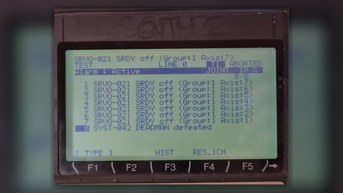
FANUC robot repair for SRVO-021 SRDY OFF should begin with the alarm record, not immediate servo-amplifier replacement. Within the R-30iB Mate and R-30iB Mate Plus scope covered here, the alarm means HRDY is ON while SRDY remains OFF, no other alarm explains the state, and the servo amplifier magnetic contactor did not turn on as commanded. Potentially involved areas include configuration-specific connections, the emergency-stop unit, power-interruption history and the servo amplifier. This condition alone does not prove that the amplifier is damaged.
Symptoms and Scope
This article addresses SRVO-021 that appears after controller inspection, cable work, servo-amplifier service or other control-cabinet maintenance. The technical definition and diagnostic order are based on the FANUC Robot series R-30iB Mate/R-30iB Mate Plus Controller Maintenance Manual B-83525EN/07. Connector locations and procedures vary with the installed controller configuration, options and manual revision.
The guidance should not be automatically applied to another FANUC controller family. It also does not cover motor, feedback or mechanical diagnosis unless an earlier or associated alarm supports that direction. A robot that cannot enable after cabinet service may have a disturbed connection or configuration issue, but the timing of the event is evidence for investigation rather than proof of a specific cause.
Information to Record First
Preserve the alarm history before resetting, cycling power or changing connections. The complete code, Group and Axis identify the affected control path, while the event sequence can reveal whether another alarm occurred before SRVO-021.
Complete alarm code and full text: Record the complete displayed message.
Date and exact time: Use the controller record and site maintenance log.
Faulted axis: Record the displayed Group and Axis.
Robot position/posture: Note the stopped position without moving the robot solely to recreate the fault.
Program step or motion: Record whether the alarm appeared during startup, enable or program execution.
Actual speed and load condition: Record the displayed or commanded condition when available.
Reset result: State whether reset was accepted and whether servo enable remained unavailable.
Time until recurrence: Record immediate or delayed recurrence without repeatedly provoking the event.
Related power, communication or feedback alarms: Preserve earlier and associated entries in their original order.
Safety and Preparation
Follow the applicable FANUC documentation, site lockout procedure and electrical safety requirements before opening the controller or touching internal connections. Stored electrical energy and unexpected robot movement can remain hazardous after power removal. Internal inspection should be performed only by suitably competent personnel using the procedure for the exact controller configuration.
Do not repeatedly command servo enable merely to reproduce SRVO-021. Before any intervention, identify the robot model, controller model, installed options, servo-amplifier label and the work completed immediately before the alarm appeared.
FANUC Robot Repair Diagnostic Sequence
- Confirm the complete alarm. Record SRVO-021, its full text, Group and Axis. If the code or affected group is missing, retrieve the event log before selecting components for inspection.
- Identify any earlier alarm. Review the chronological alarm history rather than treating SRVO-021 as an isolated event. When an earlier alarm explains why SRDY remained OFF, investigate that alarm first. Expand toward motor, feedback or mechanical systems only when the recorded alarm sequence supports that branch.
- Confirm HRDY and SRDY. Use the diagnostic screen or maintenance records when available. The documented SRVO-021 condition requires HRDY to be ON while SRDY remains OFF and no other alarm to explain the state. If those conditions are not confirmed, recheck the complete alarm record and controller-specific troubleshooting information.
- Inspect configuration-specific connections. Compare disturbed plugs, harnesses and option connections with the documentation for the installed controller. Check for incomplete seating, displaced locking features, visible contamination, bent contacts or cable damage without altering unidentified wiring. Do not apply connector names from a different controller arrangement. Names such as CP5A, CRMA92, CRMB22, CRMA91 or auxiliary-axis CXA2A/CXA2B should be used only after the exact configuration and matching manual version have been confirmed.
- Check for an instantaneous power interruption. Review the alarm time against machine power records and maintenance activity. If evidence confirms an instantaneous interruption, follow the applicable controller procedure. If records are unavailable, classify this branch as unverified rather than assuming a power event occurred.
- Evaluate the emergency-stop unit and servo amplifier. Proceed in the order and by the methods specified for the installed system. The inspection input should include the confirmed HRDY/SRDY state, event sequence, connection status and component identification. Professional testing or repair may be appropriate when external causes have not explained the condition, but SRVO-021 alone is not a conclusive amplifier diagnosis.
When Repair or Replacement May Be Considered
Consider component-level assessment when the configuration is verified, relevant connections are correct, the documented power-interruption branch has been evaluated and the alarm remains repeatable under an authorized test procedure. Before sourcing an amplifier, match the exact model, part number, hardware revision and connector layout. A visually similar unit may not be compatible with the installed controller.
Information about FANUC R-30iB servo amplifier inspection and repair is available at https://autonews.best/products/fanuc-r-30ib-si-fu-qi-ji-xiu. This resource should support identification and service planning, not replace controller-specific diagnosis.
Verification After Repair or Replacement
After authorized work, confirm that all disturbed connections are secured, protective covers are restored and tools have been removed. Review the alarm history, verify the expected enable state and perform controlled restart checks under the manufacturer operating information and site safety procedure. Motion observation, when necessary, must be performed by competent personnel in a controlled area. Do not increase speed or load merely to force recurrence. Record whether SRVO-021 returns and whether any new alarm precedes it.
Common Diagnostic Mistakes
Common errors include replacing the servo amplifier from the alarm text alone, clearing the history before recording earlier alarms, using connector references from the wrong configuration, and extending diagnosis to motors or mechanical assemblies without supporting alarms. Another mistake is assuming that a fault appearing after service proves the last handled component caused it. The service sequence narrows the inspection area, but each conclusion still requires evidence.
Information Required for a Repair Inquiry
ZHB is an independent industrial robot inspection, repair and maintenance service provider that also supplies parts to overseas customers. For one repair inquiry, provide the controller model, robot model, complete SRVO-021 text, Group and Axis, full event log, alarm time, fault conditions, connector photographs and a clear servo-amplifier label photograph. Include HRDY and SRDY status as optional information when it can be obtained from the diagnostic screen or maintenance records.
Sources and Update Information
Technical reference owner: FANUC America Corporation.
Document: FANUC Robot series R-30iB Mate/R-30iB Mate Plus Controller Maintenance Manual, B-83525EN/07, SRVO-021 SRDY off, page 73.
Accessible PDF hosted by Haas Automation: https://www.haascnc.com/content/dam/haascnc/en/service/reference/fanuc-manuals/Fanuc%20Robot%20Series%20R-30iB%20Mate%20+%20Mate%20Plus%20Maintenance%20Manual.pdf
Article updated: September 23, 2026.
Conclusion
SRVO-021 after cabinet service requires evidence-based diagnosis in the documented priority order: record the complete code with Group and Axis, identify earlier alarms, confirm HRDY and SRDY, inspect configuration-specific connections, check for an instantaneous power interruption, and then evaluate the emergency-stop unit and servo amplifier. This sequence reduces unsupported parts replacement while keeping the investigation within the applicable R-30iB Mate or R-30iB Mate Plus configuration.