
How to Repair a KUKA KR C4 Robot That Fails to Start? Troubleshooting Guide for KPP, KSP, and Control System
When a KUKA KR C4 robot experiences issues such as the control cabinet failing to start, smartPAD failing to connect, drives unable to enable, or sudden shutdown during operation, the fault may involve the control power supply, KPP power module, KSP servo drive module, control computer, RDC feedback system, and safety circuits. This article introduces the system composition of the KR C4 control cabinet, fault diagnosis sequence, key inspection points, and the restart verification process.
In this article
How to repair a KUKA KR C4 robot that fails to start? Troubleshooting guide for KPP, KSP, and the control system.
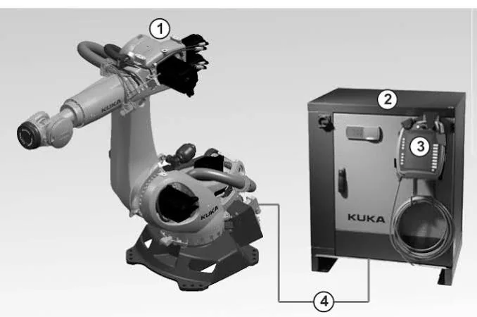
KUKA KR C4 control systems are commonly found in welding, handling, palletizing, machine tool loading/unloading, and automotive manufacturing lines. The control cabinet interior typically consists of the control computer, KPP power supply module, KSP servo drive module, safety control system, RDC position feedback system, and cooling devices.
When the robot fails to start, first determine whether the fault occurs during external power supply, control computer startup, smartPAD communication, safety condition confirmation, or drive enable phase, then inspect the corresponding components.
On-site diagnostic conclusions:
If the control cabinet shows no reaction at all, prioritize checking external power and control power; if the system can start but drives cannot be enabled, check the safety circuit, KPP, KSP, and motor links; if the robot alarms in a specific posture, then check the robot arm cable, RDC feedback lines, and mechanical interference.
Scope of application:
This article primarily applies to the KUKA KR C4 control system. Differences exist between different robot models, KSS software versions, and control cabinet configurations. Alarm meanings, measurement points, and repair requirements should be based on the equipment nameplate and the corresponding version of the technical manual.
1. Main components of the KR C4 control cabinet
Control Computer
Responsible for running the KUKA system software, robot programs, motion planning, and human-machine interaction. Control computer abnormalities may manifest as failure to start, system freeze, inability to connect the smartPAD, or programs failing to run.
KPP Power Supply Module
The KPP is responsible for the power supply and related energy management of the drive system. KPP faults may cause drives to fail to enable, bus power supply abnormalities, or multiple axes alarming simultaneously.
KSP Servo Drive Module
The KSP is responsible for controlling the servo motors for each robot axis. Module abnormalities may manifest as single-axis or multi-axis drive alarms, overcurrent, overheating, and communication faults.
RDC System
The RDC is used to collect position feedback from each robot axis and store robot-related data. RDC, battery, or feedback line abnormalities may lead to position data, zero point, or calibration-related faults.
smartPAD
The smartPAD is used to view alarms, edit programs, and manually operate the robot. Abnormalities in its cable, connectors, or internal circuitry may manifest as a black screen, unresponsive touch, communication interruption, or inability to enter the system.
2. What to record before attempting to start
Before repair, it is recommended to record:
- Robot arm model and serial number.
- Control cabinet model and KSS software version.
- Complete alarm messages displayed on the smartPAD.
- Status of indicator lights on modules inside the control cabinet.
- Whether the fault occurs during power-up, startup, or drive enable phase.
- Whether only one axis is alarming.
- Whether there have been recent power outages, collisions, or part replacements.
- Whether the fault is related to temperature, posture, or operating time.
- Complete material information for KPP, KSP, and related modules.
- Status of system program, machine data, and configuration backups.
Do not just record "robot fails to start." Specify whether the control cabinet has power, whether the system can enter the operating interface, and whether the drives can be enabled.
3. How to check if the control cabinet shows no reaction at all
If there is no obvious reaction after powering on the control cabinet, first check:
- Whether the external three-phase power supply is normal.
- Whether the main switch and circuit breakers/protection devices are in the normal state.
- Whether the incoming line terminals are loose or burnt.
- Whether the control power output is stable.
- Whether connectors inside the control cabinet are loose.
- Whether there is short circuit, moisture, or abnormal odor.
After a protection device trips, do not repeatedly close the circuit breaker directly. First check the load, power modules, and internal wiring to determine the cause of the protection trip.
The control cabinet contains high-voltage and energy-storing components. After power-off, perform lockout/tagout and wait for the specified discharge time according to the equipment manual.
4. System starts but smartPAD cannot connect
If the control cabinet has power but the smartPAD cannot enter the system normally, check:
- Whether the smartPAD display has backlight.
- Whether the cable sheath is damaged or excessively bent.
- Whether the connectors are fully locked.
- Whether the pins are bent, oxidized, or retracted.
- Whether the control computer has started normally.
- Whether the control cabinet interface power and communication are normal.
- Whether the system is stuck on the startup or recovery screen.
If the fault appears or disappears when moving the smartPAD cable, focus on checking both ends of the cable and frequently bent areas.
If the fault persists after using a confirmed normal and configuration-matched smartPAD, continue checking the control cabinet interface, control computer, and system startup status.
5. Troubleshooting methods for drives failing to enable
If the system can enter the operating interface but the robot drives cannot be enabled, first check the safety status and current alarms.
Safety circuit not satisfied
When safety gates, emergency stops, enabling switches, or external safety signals are not satisfied, the system will prohibit drive enable.
KPP power supply abnormal
If multiple axes cannot be enabled simultaneously, check the KPP module, bus power supply, related connections, and control cabinet cooling.
KSP module abnormal
If alarms are concentrated in an axis group controlled by a specific KSP, check the corresponding module, power cables, and servo motor.
Motor or power cable fault
Motor winding abnormalities, cable shorts, or connector burnouts will trigger drive protection.
Abnormal mechanical load
Brake not releasing, gearbox jamming, tool collision, or external cable pulling may also cause alarms during enable or motion phases.
6. Diagnostic directions for KPP faults
KPP-related abnormalities may manifest as:
- Multiple axes failing to enable simultaneously.
- Inability to establish the drive bus voltage.
- Power or drive alarms appearing immediately after power-up.
- Sudden loss of drive during robot operation.
- Abnormally high module temperature.
- Abnormal sounds or odors from the control cabinet.
The inspection focus includes KPP power supply, connectors, cooling fans, heat dissipation channels, and module appearance. If multiple axes alarm simultaneously, priority should be given to checking the common power supply and communication links, avoiding the replacement of motors or KSPs one by one.
Detection of the internal power circuit of the KPP should be completed by maintenance personnel with corresponding experience.
7. Judgment Directions for KSP Faults
KSP faults are typically related to the drive status of an axis group and may manifest as:
- Single axis or partial axes unable to operate.
- Drive alarm occurring at the moment of enabling.
- Overcurrent during acceleration or heavy load.
- Overheat alarm after running for a period.
- Drive module communication abnormality.
- Robot motion jitter or sudden stop.
If an alarm occurs immediately upon power-up, focus inspection on the KSP, power cables, and motor. If an alarm occurs during high speed or heavy load, increase inspection of tool load, mechanical resistance, and heat dissipation status.
KSP modules of the same appearance may have configuration and specification differences. Verify complete material information and control cabinet configuration before replacement.
8. RDC and Position Feedback Faults
When the RDC or feedback circuit is abnormal, the robot may exhibit:
- Abnormal axis position data.
- Calibration or zero-point related alarms.
- Robot unable to confirm current position.
- Loss of feedback signal for a specific axis.
- Intermittent alarms in specific postures.
- Position issues after battery replacement or power loss.
Inspection focus includes:
- RDC connectors and cables.
- Robot body cables.
- Encoder or resolver feedback circuits.
- Battery and its connection status.
- Interface between the body and control cabinet.
- Presence of moisture, oil contamination, or mechanical crushing.
If the fault is clearly related to the robot posture, priority should be given to inspecting moving cables. Even with intact outer insulation, internal conductors may develop intermittent contact due to long-term bending.
9. Judgment Directions Based on Fault Occurrence Stage
【Control cabinet completely unresponsive after power-up】
Priority checks: External power supply, main switch, control power supply, and internal wiring.
【Control cabinet starts but smartPAD cannot enter the system】
Priority checks: smartPAD cable, control computer, communication interface, and system boot status.
【System normal but drive cannot be enabled】
Priority checks: Emergency stop, safety circuit, KPP, KSP, and drive power supply.
【Only one axis alarms】
Priority checks: Corresponding KSP channel, motor, power line, feedback line, and mechanical load.
【Multiple axes alarm simultaneously】
Priority checks: KPP, common power supply, communication links, and control system.
【Alarm when moving to a fixed posture】
Priority checks: Body cables, RDC feedback lines, and mechanical interference.
【Stops after running for a period】
Priority checks: Fans, filter mats, KPP and KSP temperature rise, and motor load.
10. Control Cabinet Heat Dissipation Inspection
The stable operation of KPP, KSP, and the control computer relies on the control cabinet's heat dissipation system.
During maintenance, check:
- Whether the filter mat is clogged.
- Whether the fans are rotating normally.
- Whether the fans have abnormal noise.
- Whether the air intake and exhaust vents are blocked.
- Whether the control cabinet door and seals are intact.
- Whether dust has accumulated on module surfaces.
- Whether the ambient temperature exceeds equipment requirements.
- Whether the control cabinet air conditioner or heat exchange unit is functioning normally.
Do not use leaving the control cabinet door open long-term as a cooling method. This disrupts airflow and increases the risk of dust, oil contamination, and metal debris entering.
11. KR C4 Fault Repair Process
Step 1: Save alarm information and on-site photos.
Step 2: Record robot, control cabinet, and KSS versions.
Step 3: Back up programs, machine data, and configurations.
Step 4: Check external power supply and control power supply.
Step 5: Confirm control computer and smartPAD boot status.
Step 6: Check emergency stop and safety circuit.
Step 7: Check KPP, KSP, and drive lines.
Step 8: Check RDC, feedback lines, and body cables.
Step 9: Eliminate motor, gearbox, and external mechanical interference.
Step 10: Repair confirmed damaged components and complete recommissioning verification.
12. Recommissioning Verification After Repair
After repair completion, verify in sequence:
- Control cabinet internal wiring and module installation status.
- Fans, filtration devices, and heat dissipation channels.
- Whether the system can boot stably.
- smartPAD display, buttons, and communication functions.
- Emergency stop, safety gate, and confirmation switches.
- Current alarm status of KPP and KSP.
- Robot calibration and position data.
- Low-speed forward and reverse operation of each axis.
- Multi-axis coordinated motion program under no load.
- Operation with actual tool and workpiece under load.
- Positioning and production quality of process samples.
- Module and motor temperature rise after continuous operation.
Alarm disappearance does not signify repair completion. Only after the control system, safety functions, axis motion, and actual process are all verified as normal can automatic production be resumed.
13. Common Questions
Does a KUKA KR C4 failing to start always indicate a damaged control computer?
Not necessarily. External power supply, control power supply, smartPAD communication, internal connections, and system boot data can all cause similar phenomena.
If multiple axes cannot be enabled simultaneously, what should be checked first?
Priority should be given to checking safety status, KPP, common power supply, and communication links. It is not advisable to first conclude that multiple servo motors are damaged simultaneously.
What causes a robot to alarm only in a fixed posture?
There is a higher likelihood of body cables and feedback lines being crushed or stretched in specific postures. Mechanical interference should also be investigated.
Can production resume directly after KSP replacement?
Material and configuration compatibility must still be confirmed, and safety functions, low-speed single-axis operation, no-load coordinated motion, operation under load, and process verification must be completed.
14. Summary
When a KUKA KR C4 robot fails to start, the corresponding system should be checked based on the fault stage. For a complete lack of power, first check the external power supply and control power supply; if the system starts but the drives cannot be enabled, check the safety circuit, KPP, and KSP; for fixed posture alarms, focus on checking the RDC, robot body cables, and mechanical interference.
Technical content reference: KUKA KR C4 control system structure, equipment technical documentation, and industrial robot on-site repair experience
Content update time: September 2026
Repair Consultation
If you need to repair a KUKA KR C4 control cabinet, KPP, KSP, smartPAD, or robot body, please provide the robot model, control cabinet model, KSS version, complete alarm information, module nameplate, and on-site photos or videos.
Industrial Robot Repair Hotline: +86 18122009539
Contact Repair Engineer: +86 18122009539
Need a part or repair assessment?
Share the robot model, part number, fault details and destination country with our team.
Contact our team ↗